
Loose Leaf for Engineering Circuit Analysis Format: Loose-leaf
9th Edition
ISBN: 9781259989452
Author: Hayt
Publisher: Mcgraw Hill Publishers
expand_more
expand_more
format_list_bulleted
Concept explainers
Videos
Textbook Question
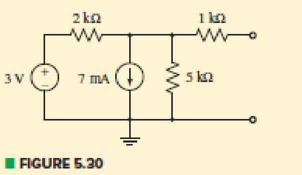
Chapter 5.3, Problem 7P
Determine the Thévenin and Norton equivalents of the circuit of Fig. 5.30.
Expert Solution & Answer
Want to see the full answer?
Check out a sample textbook solution
Students have asked these similar questions
fig. 5.40
transform using source transformation
*42. Given the information appcaring in Fig. 5.128, find the
level of resistance for R, and R3.
Q +12 V
Ri
+4 V
R2
-4 V
Ry
-8 V
5.66 For the circuit in Fig. 5.93, find v.
25 kQ
40 k2
100 k2
20 k2
20 k2
12 V
10 k2
8 V
4 V
Chapter 5 Solutions
Loose Leaf for Engineering Circuit Analysis Format: Loose-leaf
Ch. 5.1 - For the circuit of Fig. 5.4, use superposition to...Ch. 5.2 - For the circuit of Fig. 5.7, use superposition to...Ch. 5.2 - For the circuit of Fig. 5.18, compute the current...Ch. 5.2 - For the circuit of Fig. 5.20, compute the voltage...Ch. 5.3 - Using repeated source transformations, determine...Ch. 5.3 - Use Thvenins theorem to find the current through...Ch. 5.3 - Determine the Thvenin and Norton equivalents of...Ch. 5.3 - Find the Thvenin equivalent for the network of...Ch. 5.3 - Find the Thvenin equivalent for the network of...Ch. 5.4 - Consider the circuit of Fig. 5.43. FIGURE 5.43...
Ch. 5.5 - Prob. 11PCh. 5 - Linear systems are so easy to work with that...Ch. 5 - Prob. 2ECh. 5 - Prob. 3ECh. 5 - (a) Employ superposition to determine the current...Ch. 5 - (a) Using superposition to consider each source...Ch. 5 - (a) Determine the individual contributions of each...Ch. 5 - (a) Determine the individual contributions of each...Ch. 5 - After studying the circuit of Fig. 5.53, change...Ch. 5 - Consider the three circuits shown in Fig. 5.54....Ch. 5 - (a) Using superposition, determine the voltage...Ch. 5 - Employ superposition principles to obtain a value...Ch. 5 - (a) Employ superposition to determine the...Ch. 5 - Perform an appropriate source transformation on...Ch. 5 - (a) For the circuit of Fig. 5.59, plot iL versus...Ch. 5 - Determine the current labeled I in the circuit of...Ch. 5 - Verify that the power absorbed by the 7 resistor...Ch. 5 - (a) Determine the current labeled i in the circuit...Ch. 5 - (a) Using repeated source transformations, reduce...Ch. 5 - Prob. 19ECh. 5 - (a) Making use of repeated source transformations,...Ch. 5 - Prob. 21ECh. 5 - (a) With the assistance of source transformations,...Ch. 5 - For the circuit in Fig. 5.67 transform all...Ch. 5 - Prob. 24ECh. 5 - (a) Referring to Fig. 5.69, determine the Thevenin...Ch. 5 - (a) With respect to the circuit depicted in Fig....Ch. 5 - (a) Obtain the Norton equivalent of the network...Ch. 5 - (a) Determine the Thevenin equivalent of the...Ch. 5 - Referring to the circuit of Fig. 5.71: (a)...Ch. 5 - Prob. 30ECh. 5 - (a) Employ Thvenins theorem to obtain a...Ch. 5 - Prob. 32ECh. 5 - Determine the Norton equivalent of the circuit...Ch. 5 - For the circuit of Fig. 5.75: (a) Employ Nortons...Ch. 5 - (a) Obtain a value for the Thvenin equivalent...Ch. 5 - Prob. 36ECh. 5 - Obtain a value for the Thvenin equivalent...Ch. 5 - With regard to the network depicted in Fig. 5.79,...Ch. 5 - Determine the Thvenin and Norton equivalents of...Ch. 5 - Determine the Norton equivalent of the circuit...Ch. 5 - Prob. 41ECh. 5 - Determine the Thvenin and Norton equivalents of...Ch. 5 - Prob. 43ECh. 5 - Prob. 44ECh. 5 - Prob. 45ECh. 5 - (a) For the simple circuit of Fig. 5.87, find the...Ch. 5 - For the circuit drawn in Fig. 5.88, (a) determine...Ch. 5 - Study the circuit of Fig. 5.89. (a) Determine the...Ch. 5 - Prob. 49ECh. 5 - Prob. 50ECh. 5 - With reference to the circuit of Fig. 5.91, (a)...Ch. 5 - Prob. 52ECh. 5 - Select a value for RL in Fig. 5.93 such that it...Ch. 5 - Determine what value of resistance would absorb...Ch. 5 - Derive the equations required to convert from a...Ch. 5 - Convert the - (or "-") connected networks in Fig....Ch. 5 - Convert the Y-(or T-) connected networks in Fig....Ch. 5 - For the network of Fig. 5.97, select a value of R...Ch. 5 - For the network of Fig. 5.98, select a value of R...Ch. 5 - Prob. 60ECh. 5 - Calculate Rin as indicated in Fig.5.100. FIGURE...Ch. 5 - Employ Y conversion techniques as appropriate to...Ch. 5 - Prob. 63ECh. 5 - (a) Use appropriate techniques to obtain both the...Ch. 5 - (a) For the network in Fig. 5.104, replace the...Ch. 5 - Prob. 66ECh. 5 - Prob. 67ECh. 5 - A 2.57 load is connected between terminals a and...Ch. 5 - A load resistor is connected across the open...Ch. 5 - A backup is required for the circuit depicted in...Ch. 5 - (a) Explain in general terms how source...Ch. 5 - The load resistor in Fig. 5.108 can safely...Ch. 5 - Prob. 74ECh. 5 - As part of a security system, a very thin 100 ...Ch. 5 - With respect to the circuit in Fig. 5.90, (a)...
Knowledge Booster


Learn more about
Need a deep-dive on the concept behind this application? Look no further. Learn more about this topic, electrical-engineering and related others by exploring similar questions and additional content below.Similar questions
- demonstrate how to find V, in the circuit in Fig. 5.15a using the repeated application of source transformation. ww ww 3 k 2 k 4 kf (1)2 mA 38 k V. 12V (a)arrow_forwardQ 3. State the Thevenin's theorem and draw the Thevenin equivalent circuit cross the 62 load resistance shown in Fig 5. 12V 2 A Fig.5arrow_forwardlearn-us-east-1-prod-fleet01-xythos.s3.amazonaws.com http https://learn-us-east-1-prod-fleet01-xythos.s.. Untitled Untitled PROBLEMS SECTION 5.2 Series Resistors 1. For each configuration in Fig. 5.88, find the individual (not combinations of) elements (voltage sources and/or resis- tors) that are in series. R1 R1 R3 { E E R2 R3 R2 (a) (b) R2 R3 R1 R1 R3 R2 RA E2 E E R5 (d) (c) FIG. 5.88 Problem 1. 2. For each configuration in Dis MacBook Pro & 2$ 8 9 @ # 6 7 4 5 3 Y U T E P R W/ 2.arrow_forward
- 5.2 For the circuit of Fig. 5.7, use superposition to obtain the voltage across each current source. Ans: Viha = 9.180 V, v2zA =-1.148 V, UIlay = 1.967 V, v2by = -0.246 V; vI = 11.147 V, vz = -1.394 V. %3D %3D %3D 15 N 12 4i 2 A( 3 Varrow_forwardFor the cascaded system of Fig. 5.177 with two identical stages, determine TOTAL VOLTAGE GAIN OF THE SYSTEM. IμF R₁ 1µF ww 0.6 k2 CE amplifier HE CE amplifier Z-1 ke Z₁-1kQ 12 Z₂-3.3kQ Z R₁2.7k Z₂-33kQ Z AV-420 AV-420 Zo₁ FIG. 5.177 P Select one: O a. Av = 18. 46 x 10^3 O b. Av = 13. 64 x 10^3 O c. Av = 16. 45 X 10^3 O d. Av = 11.54 x 10^3 rarrow_forwardFor the circuit in Fig. 5.88, composed of standard values: a. Which resistor will have the most impact on the total resistance? b. On an approximate basis, which resistors can be ignored when determining the total resistance? c. Find the total resistance, and comment on your results for parts (a) and (b).arrow_forward
- 1. For each configuration in Fig. 5.88, find the individaal (not combinations of) elements (voltage sources and/or resis- Lors) that are in serics. N R (a) (b) (e) (4) 一章arrow_forwardHW22 Using Fig. 5.75, design a problem to help other students better understand summing amplifiers. Vị R1 V2 R2 ww V3 R3 ww R5 V4 R4 니arrow_forwardFor the series configuration in Fig. 5.92, constructed using standard value resistors: a.) Without making a single calculation, which resistive element will have the most voltage across it? Which will have the least? b.) Which resistor will have the most impact on the total resistance and the resulting current? Find the total resistance and the current.arrow_forward
- 24. With regard to the circuit represented in Fig. 5.68, first transform both voltage sources to current sources, reduce the number of elements as much as possible, and determine the voltage v3. 6 0 + V3 203 2 Varrow_forwardLMH_chapter3-part 1-homework [Protected View] PowerPoint ĐĂNG PHẠM HỒNG File Home Insert Design Transitions Animations Slide Show Review View Help Tell me what you want to do & Share 1 Chapter III HW15 AC Circuit Analysis Homework part 1 Reading: Chapter 05 Textbook: Fundamental of Electric Circuits Textbook 5.10 Find the gain v,/v, of the circuit in Fig. 5.49. 2 HW14 5.7 The op amp in Fig 5.46 has R, - 100 k, R, - 100 2, 4- 100,000. Find dhe dillerential volage e, and the output voltage v. 37 k2 10 k 100 A 20 kΩ I mv :) 3. HW15 5.10 Find the gain r/v, of the circait in Fig. 5.49. 10 k2 37 ko 20 k2 4 HW16 5.13 Find u, andi, in the circuit of Fig. 5.52. 3 1v O 100 k2 E90 ka 10 k2 50 kaarrow_forwardĐĂNG PHẠM HỒNG PowerPoint LMH_chapter3-part 1-homework [Protected View] & Share View Help Tell me what you want to do Home Insert Design Transitions Animations Slide Show Review File HW17 5.14 Determine the output voltage v, in dhe circuit of Fig 5.53. HW19 10 ka ww 10 ka 20 ka S ma () 5ko 5.24 In the circuit shown in Fig. 5.62, find k in the voltage transfer function vo = ku;. 6. HW18 Ry 5.20 In the circuit of Fig. 5.59, calculate v, of v; = 0. S kl ww ww 2 kS ww R1 R2 9v e 7 HW19 3.24 In the circuit shown in Fig 5.62, find k in the voltage transfer flunction ,- b, R3 8. HW20 5.32 Calculate ir and v, in the cicuit of Fir. 5.70. Find the power dissipated by the 30 k resistor 7 43 a 4 mV ( 60 k2 30 k2arrow_forward
arrow_back_ios
SEE MORE QUESTIONS
arrow_forward_ios
Recommended textbooks for you
 Introductory Circuit Analysis (13th Edition)Electrical EngineeringISBN:9780133923605Author:Robert L. BoylestadPublisher:PEARSON
 Delmar's Standard Textbook Of ElectricityElectrical EngineeringISBN:9781337900348Author:Stephen L. HermanPublisher:Cengage Learning
 Programmable Logic ControllersElectrical EngineeringISBN:9780073373843Author:Frank D. PetruzellaPublisher:McGraw-Hill Education
 Fundamentals of Electric CircuitsElectrical EngineeringISBN:9780078028229Author:Charles K Alexander, Matthew SadikuPublisher:McGraw-Hill Education
 Electric Circuits. (11th Edition)Electrical EngineeringISBN:9780134746968Author:James W. Nilsson, Susan RiedelPublisher:PEARSON
 Engineering ElectromagneticsElectrical EngineeringISBN:9780078028151Author:Hayt, William H. (william Hart), Jr, BUCK, John A.Publisher:Mcgraw-hill Education,
Introductory Circuit Analysis (13th Edition)
Electrical Engineering
ISBN:9780133923605
Author:Robert L. Boylestad
Publisher:PEARSON
Delmar's Standard Textbook Of Electricity
Electrical Engineering
ISBN:9781337900348
Author:Stephen L. Herman
Publisher:Cengage Learning
Programmable Logic Controllers
Electrical Engineering
ISBN:9780073373843
Author:Frank D. Petruzella
Publisher:McGraw-Hill Education
Fundamentals of Electric Circuits
Electrical Engineering
ISBN:9780078028229
Author:Charles K Alexander, Matthew Sadiku
Publisher:McGraw-Hill Education
Electric Circuits. (11th Edition)
Electrical Engineering
ISBN:9780134746968
Author:James W. Nilsson, Susan Riedel
Publisher:PEARSON
Engineering Electromagnetics
Electrical Engineering
ISBN:9780078028151
Author:Hayt, William H. (william Hart), Jr, BUCK, John A.
Publisher:Mcgraw-hill Education,
Z Parameters - Impedance Parameters; Author: Electrical Engineering Authority;https://www.youtube.com/watch?v=qoD4AoNmySA;License: Standard Youtube License