
Loose Leaf for Engineering Circuit Analysis Format: Loose-leaf
9th Edition
ISBN: 9781259989452
Author: Hayt
Publisher: Mcgraw Hill Publishers
expand_more
expand_more
format_list_bulleted
Concept explainers
Videos
Textbook Question
Chapter 5.2, Problem 3P
For the circuit of Fig. 5.18, compute the current IX through the 47 kΩ resistor after performing a source transformation on the voltage source.
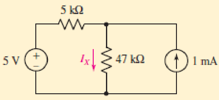
■ FIGURE 5.18
Expert Solution & Answer
Want to see the full answer?
Check out a sample textbook solution
Students have asked these similar questions
LMH_chapter3-part 1-homework [Protected View]
PowerPoint
ĐĂNG PHẠM HỒNG
File
Home
Insert
Design
Transitions
Animations
Slide Show
Review
View
Help
Tell me what you want to do
& Share
6.
HW18
5.20 In the circuit of Fig. 5.59, calculate v, of v; = 0.
HW20
8 ka
4
4 ka
5.32 Calculate iz and v, in the circuit of Fig. 5.70. Find
the power dissipated by the 30-kN resistor.
7
HW19
3.24 In the circuit shown in Fig 5.62, find k in the voltage
transfer flunction ,- ,
48 k2
ww
ww
8
4 mV
50 k2
HW20
60 k2
30 Ω
5.32 Calculate i, and e, in the circuit of Fig. 5.70. Find
the power dissipated by the 30 kl resistor
10 kΩ
4 mv (
50 ka
60
30 k2
10 k2
9.
HW21
5.33 Re:kn lo the p m tineuit in Fip 571 Caknulale4
ud the pomer disupated by dhe kil resistor.
1 kI
8
3 ma O
ww-
ww
Digital lab & design
The circuits don’t have to be created in proteus project just a normal drawing on paper will do, thanks.
3)
how long will it take to charge a 1000μF capacitor through 1 KQ resistor to
full 16V source voltage? d) forever
a) 1000 microseconds
b) 10seconds
c) one day
d)
forever
What maximum voltage can be safely applied to series resistors, 1.2 KQ ¹4 W
and 680 0%W?
a) 9.81V
b) 17.32. V
c)27.07 V
d) 32.52V
When a capacitor is being charged from a 12V power source, the current
flowing through thecapacitor will
a} increase
b} decrease
c) remain the same
d) can't be determined
Calculate the voltmeter reading in the circuit shown in the figure when wiper
arm of the potentiometer is set at 25% up fromthe bottom. note: the
resistance value is 3.3 Kilo-ohms.
9V
Oa) 2.13 V
b) 3.12 V
c)2.31 V
d) 6.25 V
1k
3k3
Chapter 5 Solutions
Loose Leaf for Engineering Circuit Analysis Format: Loose-leaf
Ch. 5.1 - For the circuit of Fig. 5.4, use superposition to...Ch. 5.2 - For the circuit of Fig. 5.7, use superposition to...Ch. 5.2 - For the circuit of Fig. 5.18, compute the current...Ch. 5.2 - For the circuit of Fig. 5.20, compute the voltage...Ch. 5.3 - Using repeated source transformations, determine...Ch. 5.3 - Use Thvenins theorem to find the current through...Ch. 5.3 - Determine the Thvenin and Norton equivalents of...Ch. 5.3 - Find the Thvenin equivalent for the network of...Ch. 5.3 - Find the Thvenin equivalent for the network of...Ch. 5.4 - Consider the circuit of Fig. 5.43. FIGURE 5.43...
Ch. 5.5 - Prob. 11PCh. 5 - Linear systems are so easy to work with that...Ch. 5 - Prob. 2ECh. 5 - Prob. 3ECh. 5 - (a) Employ superposition to determine the current...Ch. 5 - (a) Using superposition to consider each source...Ch. 5 - (a) Determine the individual contributions of each...Ch. 5 - (a) Determine the individual contributions of each...Ch. 5 - After studying the circuit of Fig. 5.53, change...Ch. 5 - Consider the three circuits shown in Fig. 5.54....Ch. 5 - (a) Using superposition, determine the voltage...Ch. 5 - Employ superposition principles to obtain a value...Ch. 5 - (a) Employ superposition to determine the...Ch. 5 - Perform an appropriate source transformation on...Ch. 5 - (a) For the circuit of Fig. 5.59, plot iL versus...Ch. 5 - Determine the current labeled I in the circuit of...Ch. 5 - Verify that the power absorbed by the 7 resistor...Ch. 5 - (a) Determine the current labeled i in the circuit...Ch. 5 - (a) Using repeated source transformations, reduce...Ch. 5 - Prob. 19ECh. 5 - (a) Making use of repeated source transformations,...Ch. 5 - Prob. 21ECh. 5 - (a) With the assistance of source transformations,...Ch. 5 - For the circuit in Fig. 5.67 transform all...Ch. 5 - Prob. 24ECh. 5 - (a) Referring to Fig. 5.69, determine the Thevenin...Ch. 5 - (a) With respect to the circuit depicted in Fig....Ch. 5 - (a) Obtain the Norton equivalent of the network...Ch. 5 - (a) Determine the Thevenin equivalent of the...Ch. 5 - Referring to the circuit of Fig. 5.71: (a)...Ch. 5 - Prob. 30ECh. 5 - (a) Employ Thvenins theorem to obtain a...Ch. 5 - Prob. 32ECh. 5 - Determine the Norton equivalent of the circuit...Ch. 5 - For the circuit of Fig. 5.75: (a) Employ Nortons...Ch. 5 - (a) Obtain a value for the Thvenin equivalent...Ch. 5 - Prob. 36ECh. 5 - Obtain a value for the Thvenin equivalent...Ch. 5 - With regard to the network depicted in Fig. 5.79,...Ch. 5 - Determine the Thvenin and Norton equivalents of...Ch. 5 - Determine the Norton equivalent of the circuit...Ch. 5 - Prob. 41ECh. 5 - Determine the Thvenin and Norton equivalents of...Ch. 5 - Prob. 43ECh. 5 - Prob. 44ECh. 5 - Prob. 45ECh. 5 - (a) For the simple circuit of Fig. 5.87, find the...Ch. 5 - For the circuit drawn in Fig. 5.88, (a) determine...Ch. 5 - Study the circuit of Fig. 5.89. (a) Determine the...Ch. 5 - Prob. 49ECh. 5 - Prob. 50ECh. 5 - With reference to the circuit of Fig. 5.91, (a)...Ch. 5 - Prob. 52ECh. 5 - Select a value for RL in Fig. 5.93 such that it...Ch. 5 - Determine what value of resistance would absorb...Ch. 5 - Derive the equations required to convert from a...Ch. 5 - Convert the - (or "-") connected networks in Fig....Ch. 5 - Convert the Y-(or T-) connected networks in Fig....Ch. 5 - For the network of Fig. 5.97, select a value of R...Ch. 5 - For the network of Fig. 5.98, select a value of R...Ch. 5 - Prob. 60ECh. 5 - Calculate Rin as indicated in Fig.5.100. FIGURE...Ch. 5 - Employ Y conversion techniques as appropriate to...Ch. 5 - Prob. 63ECh. 5 - (a) Use appropriate techniques to obtain both the...Ch. 5 - (a) For the network in Fig. 5.104, replace the...Ch. 5 - Prob. 66ECh. 5 - Prob. 67ECh. 5 - A 2.57 load is connected between terminals a and...Ch. 5 - A load resistor is connected across the open...Ch. 5 - A backup is required for the circuit depicted in...Ch. 5 - (a) Explain in general terms how source...Ch. 5 - The load resistor in Fig. 5.108 can safely...Ch. 5 - Prob. 74ECh. 5 - As part of a security system, a very thin 100 ...Ch. 5 - With respect to the circuit in Fig. 5.90, (a)...
Additional Engineering Textbook Solutions
Find more solutions based on key concepts
Explain the main function of each of the following major components of a PLC: a. Processor module (CPU) b. I/O ...
Programmable Logic Controllers
For the “tank” circuit in Fig. 14.79, find the resonant frequency.
Figure 14.79
For Probs. 14.39, 14.71, and 1...
Fundamentals of Electric Circuits
Three point charges of equal magnitude q, that will yield a zero net electric field at the origin.
Engineering Electromagnetics
Assume a telephone signal travels through a cable at two-thirds the speed of light. How long does it take the s...
Electric Circuits (10th Edition)
The current source in the circuit shown generates the current pulse
Find (a) v (0); (b) the instant of time gr...
Electric Circuits. (11th Edition)
What is the color code for a 365- five-band precision resistor with a tolerance of 5 percent?
ELECTRICITY FOR TRADES (LOOSELEAF)
Knowledge Booster


Learn more about
Need a deep-dive on the concept behind this application? Look no further. Learn more about this topic, electrical-engineering and related others by exploring similar questions and additional content below.Similar questions
- how long will it take to charge a 1000μF capacitor through 1 KQ resistor to full 16V source voltage? d) forever a) 1000 microseconds b) 10seconds c) one day d) forever What maximum voltage can be safely applied to series resistors, 1.2 KQ 14 W and 680 0%W? a) 9.81V b) 17.32. V c)27.07 V d) 32.52V When a capacitor is being charged from a 12V power source, the current flowing through thecapacitor will a} increase b} decrease c) remain the same d) can't be determined Calculate the voltmeter reading in the circuit shown in the figure when wiper arm of the potentiometer is set at 25% up fromthe bottom. note: the resistance value is 3.3 Kilo-ohms. 9V a) 2.13 V b) 3.12 V c)2.31 V d) 6.25 V 1k 3k3arrow_forwardGiven the circuit below. The current through the 100 resistor in the circuit below is 8.0 mA. Determine the 2002 5.0 (2 [www] 10:2 a) total resistance b) total current c) total voltage 30 2 www wwww 5.002 4002arrow_forwardLMH_chapter3-part 1-homework [Protected View] PowerPoint ĐĂNG PHẠM HỒNG File Home Insert Design Transitions Animations Slide Show Review View Help Tell me what you want to do & Share 4 HW16 5.13 Find u, and i, in the circuit of Fig. 5.52. HW18 10 ka 1vO 100 ka 90 ka 10 ka 5.20 In the circuit of Fig. 5.59, calculate v, of v; = 0. 50 k2 8 kQ HW17 ww 5.14 Determine the output voltage v, in the circuit of 5.53. 10 ka 2 k2 10 ka 20 ka 4 k2 4 k2 Sma O 5 kQ www ww 6. 9 V HW18 5.20 In the circuit of Fig. 5.59, calculate v, of v; = 0. 8 ka 4 ka 4 ka ww 7 HW19 3.24 In the circuit shown in Fig. 5.62, find k in the voltage tYansfer flunction ,- b, R. 6. ww-arrow_forward
- 24. With regard to the circuit represented in Fig. 5.68, first transform both voltage sources to current sources, reduce the number of elements as much as possible, and determine the voltage v3. 6 0 + V3 203 2 Varrow_forward5.2 For the circuit of Fig. 5.7, use superposition to obtain the voltage across each current source. Ans: Viha = 9.180 V, v2zA =-1.148 V, UIlay = 1.967 V, v2by = -0.246 V; vI = 11.147 V, vz = -1.394 V. %3D %3D %3D 15 N 12 4i 2 A( 3 Varrow_forwardDesign a charger circuit for mobile phone from:1.5 V AA BatterySelect the proper circuit topologies and components. (please explain in detail)arrow_forward
- Determine the Equivalent Resistance (Rab) of the circuit. ( please provide illustrations/drawings it is needed for our solutions)arrow_forwardO 50 15. Why should design our circuits to operate below the SRF of electrical elements? to increase the gain to make the circuit simple None of them to reduce the power used in the circuit. to avoid the unexpected behavoir Clear form Page 1 of 1 Submit Never submit passwords through Google Forms.arrow_forwardConsider a 2.5kW PV system exposed to sun for 6 hours with the solar intensity of 1 sun. Calculate the total PV power generation for 3 years. Also, calculate the loss in PV power generation if the solar intensity is reduced to 0.8 sun and 0.5 sun. [Estimated time to solve: 8 min]arrow_forward
- Question 18 a) Using repeated source transformations, reduce the circuit of Fig. 5.62 to a voltage source in series with a resistor, both of which are in series with the 6 MS2 resistor. b) Calculate the power dissipated by the 6 MS2 resistor using your simplified circuit. 27 ΜΑ (1) FIGURE 5.62 3.5 ΜΩ www 750 ΚΩ 1.2 ΜΩ 15 V 7 ΜΩ 6 ΜΩarrow_forwardWhich of the following elements of electrical engineering cannot be analyzed using Ohm's law? a) Capacitors b) Inductors c) Transistors d) Resistancearrow_forwardIf no node was encountered more than once, then the set of nodes and elements that we have passed through is defined as a closed path. Select one: O True Falsearrow_forward
arrow_back_ios
SEE MORE QUESTIONS
arrow_forward_ios
Recommended textbooks for you
 Introductory Circuit Analysis (13th Edition)Electrical EngineeringISBN:9780133923605Author:Robert L. BoylestadPublisher:PEARSON
 Delmar's Standard Textbook Of ElectricityElectrical EngineeringISBN:9781337900348Author:Stephen L. HermanPublisher:Cengage Learning
 Programmable Logic ControllersElectrical EngineeringISBN:9780073373843Author:Frank D. PetruzellaPublisher:McGraw-Hill Education
 Fundamentals of Electric CircuitsElectrical EngineeringISBN:9780078028229Author:Charles K Alexander, Matthew SadikuPublisher:McGraw-Hill Education
 Electric Circuits. (11th Edition)Electrical EngineeringISBN:9780134746968Author:James W. Nilsson, Susan RiedelPublisher:PEARSON
 Engineering ElectromagneticsElectrical EngineeringISBN:9780078028151Author:Hayt, William H. (william Hart), Jr, BUCK, John A.Publisher:Mcgraw-hill Education,
Introductory Circuit Analysis (13th Edition)
Electrical Engineering
ISBN:9780133923605
Author:Robert L. Boylestad
Publisher:PEARSON
Delmar's Standard Textbook Of Electricity
Electrical Engineering
ISBN:9781337900348
Author:Stephen L. Herman
Publisher:Cengage Learning
Programmable Logic Controllers
Electrical Engineering
ISBN:9780073373843
Author:Frank D. Petruzella
Publisher:McGraw-Hill Education
Fundamentals of Electric Circuits
Electrical Engineering
ISBN:9780078028229
Author:Charles K Alexander, Matthew Sadiku
Publisher:McGraw-Hill Education
Electric Circuits. (11th Edition)
Electrical Engineering
ISBN:9780134746968
Author:James W. Nilsson, Susan Riedel
Publisher:PEARSON
Engineering Electromagnetics
Electrical Engineering
ISBN:9780078028151
Author:Hayt, William H. (william Hart), Jr, BUCK, John A.
Publisher:Mcgraw-hill Education,
Z Parameters - Impedance Parameters; Author: Electrical Engineering Authority;https://www.youtube.com/watch?v=qoD4AoNmySA;License: Standard Youtube License