
Loose Leaf for Engineering Circuit Analysis Format: Loose-leaf
9th Edition
ISBN: 9781259989452
Author: Hayt
Publisher: Mcgraw Hill Publishers
expand_more
expand_more
format_list_bulleted
Concept explainers
Videos
Textbook Question
Chapter 5, Problem 26E
(a) With respect to the circuit depicted in Fig. 5.69, obtain the Norton equivalent of the network connected to RL. (b) Plot the power dissipated in resistor RL as a function of iL corresponding to the range of 0 < RL < 5 Ω. (c) Using your graph, estimate at what value of RL the dissipated power reaches its maximum value.
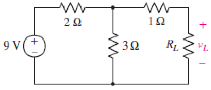
■ FIGURE 5.69
Expert Solution & Answer
Want to see the full answer?
Check out a sample textbook solution
Students have asked these similar questions
Q17. For the circuit shown in Figure 5.23
calculate (a) the value of resistor Rx such
that the total power dissipated in the circuit
is 2.5kW, and (b) the current flowing in
each of the four resistors.
4 Rq=15 2
a A3=38 2
R2=10 2
Rx
12
14
V2²
250 V
LMH_chapter3-part 1-homework [Protected View]
PowerPoint
ĐĂNG PHẠM HỒNG
File
Home
Insert
Design
Transitions
Animations
Slide Show
Review
View
Help
Tell me what you want to do
& Share
4
HW16
5.13 Find u, and i, in the circuit of Fig. 5.52.
HW18
10 ka
1vO
100 ka
90 ka
10 ka
5.20 In the circuit of Fig. 5.59, calculate v, of v; = 0.
50 k2
8 kQ
HW17
ww
5.14 Determine the output voltage v, in the circuit of
5.53.
10 ka
2 k2
10 ka
20 ka
4 k2
4 k2
Sma O
5 kQ
www
ww
6.
9 V
HW18
5.20 In the circuit of Fig. 5.59, calculate v, of v; = 0.
8 ka
4 ka
4 ka
ww
7
HW19
3.24 In the circuit shown in Fig. 5.62, find k in the voltage
tYansfer flunction ,- b,
R.
6.
ww-
Calculate the current through the 4 Ω resistor by applying MCM to the circuit below. Set up the circuit in PSIM program.
Chapter 5 Solutions
Loose Leaf for Engineering Circuit Analysis Format: Loose-leaf
Ch. 5.1 - For the circuit of Fig. 5.4, use superposition to...Ch. 5.2 - For the circuit of Fig. 5.7, use superposition to...Ch. 5.2 - For the circuit of Fig. 5.18, compute the current...Ch. 5.2 - For the circuit of Fig. 5.20, compute the voltage...Ch. 5.3 - Using repeated source transformations, determine...Ch. 5.3 - Use Thvenins theorem to find the current through...Ch. 5.3 - Determine the Thvenin and Norton equivalents of...Ch. 5.3 - Find the Thvenin equivalent for the network of...Ch. 5.3 - Find the Thvenin equivalent for the network of...Ch. 5.4 - Consider the circuit of Fig. 5.43. FIGURE 5.43...
Ch. 5.5 - Prob. 11PCh. 5 - Linear systems are so easy to work with that...Ch. 5 - Prob. 2ECh. 5 - Prob. 3ECh. 5 - (a) Employ superposition to determine the current...Ch. 5 - (a) Using superposition to consider each source...Ch. 5 - (a) Determine the individual contributions of each...Ch. 5 - (a) Determine the individual contributions of each...Ch. 5 - After studying the circuit of Fig. 5.53, change...Ch. 5 - Consider the three circuits shown in Fig. 5.54....Ch. 5 - (a) Using superposition, determine the voltage...Ch. 5 - Employ superposition principles to obtain a value...Ch. 5 - (a) Employ superposition to determine the...Ch. 5 - Perform an appropriate source transformation on...Ch. 5 - (a) For the circuit of Fig. 5.59, plot iL versus...Ch. 5 - Determine the current labeled I in the circuit of...Ch. 5 - Verify that the power absorbed by the 7 resistor...Ch. 5 - (a) Determine the current labeled i in the circuit...Ch. 5 - (a) Using repeated source transformations, reduce...Ch. 5 - Prob. 19ECh. 5 - (a) Making use of repeated source transformations,...Ch. 5 - Prob. 21ECh. 5 - (a) With the assistance of source transformations,...Ch. 5 - For the circuit in Fig. 5.67 transform all...Ch. 5 - Prob. 24ECh. 5 - (a) Referring to Fig. 5.69, determine the Thevenin...Ch. 5 - (a) With respect to the circuit depicted in Fig....Ch. 5 - (a) Obtain the Norton equivalent of the network...Ch. 5 - (a) Determine the Thevenin equivalent of the...Ch. 5 - Referring to the circuit of Fig. 5.71: (a)...Ch. 5 - Prob. 30ECh. 5 - (a) Employ Thvenins theorem to obtain a...Ch. 5 - Prob. 32ECh. 5 - Determine the Norton equivalent of the circuit...Ch. 5 - For the circuit of Fig. 5.75: (a) Employ Nortons...Ch. 5 - (a) Obtain a value for the Thvenin equivalent...Ch. 5 - Prob. 36ECh. 5 - Obtain a value for the Thvenin equivalent...Ch. 5 - With regard to the network depicted in Fig. 5.79,...Ch. 5 - Determine the Thvenin and Norton equivalents of...Ch. 5 - Determine the Norton equivalent of the circuit...Ch. 5 - Prob. 41ECh. 5 - Determine the Thvenin and Norton equivalents of...Ch. 5 - Prob. 43ECh. 5 - Prob. 44ECh. 5 - Prob. 45ECh. 5 - (a) For the simple circuit of Fig. 5.87, find the...Ch. 5 - For the circuit drawn in Fig. 5.88, (a) determine...Ch. 5 - Study the circuit of Fig. 5.89. (a) Determine the...Ch. 5 - Prob. 49ECh. 5 - Prob. 50ECh. 5 - With reference to the circuit of Fig. 5.91, (a)...Ch. 5 - Prob. 52ECh. 5 - Select a value for RL in Fig. 5.93 such that it...Ch. 5 - Determine what value of resistance would absorb...Ch. 5 - Derive the equations required to convert from a...Ch. 5 - Convert the - (or "-") connected networks in Fig....Ch. 5 - Convert the Y-(or T-) connected networks in Fig....Ch. 5 - For the network of Fig. 5.97, select a value of R...Ch. 5 - For the network of Fig. 5.98, select a value of R...Ch. 5 - Prob. 60ECh. 5 - Calculate Rin as indicated in Fig.5.100. FIGURE...Ch. 5 - Employ Y conversion techniques as appropriate to...Ch. 5 - Prob. 63ECh. 5 - (a) Use appropriate techniques to obtain both the...Ch. 5 - (a) For the network in Fig. 5.104, replace the...Ch. 5 - Prob. 66ECh. 5 - Prob. 67ECh. 5 - A 2.57 load is connected between terminals a and...Ch. 5 - A load resistor is connected across the open...Ch. 5 - A backup is required for the circuit depicted in...Ch. 5 - (a) Explain in general terms how source...Ch. 5 - The load resistor in Fig. 5.108 can safely...Ch. 5 - Prob. 74ECh. 5 - As part of a security system, a very thin 100 ...Ch. 5 - With respect to the circuit in Fig. 5.90, (a)...
Additional Engineering Textbook Solutions
Find more solutions based on key concepts
A constant voltage of 10V is applied to a 50H inductance, as shown in Figure P3.51 Figure P3 51 The current in ...
Electrical Engineering: Principles & Applications (7th Edition)
Analog Voltmeter Design Figure P2-98(a) shows a voltmeter circuit consisting of a D'Arsonval meter, two series ...
ANALYSIS+DESIGN OF LINEAR CIRCUITS(LL)
Does the severity of an electric shock increase ordecrease with eh of the following changes? a. A decrease in t...
Electric Motors and Control Systems
What is the color code for a 365- five-band precision resistor with a tolerance of 5 percent?
ELECTRICITY FOR TRADES (LOOSELEAF)
Electric power systems provide energy in a variety of commercial and industrial settings. Make a list of system...
Principles and Applications of Electrical Engineering
Three point charges of equal magnitude q, that will yield a zero net electric field at the origin.
Engineering Electromagnetics
Knowledge Booster


Learn more about
Need a deep-dive on the concept behind this application? Look no further. Learn more about this topic, electrical-engineering and related others by exploring similar questions and additional content below.Similar questions
- Question 30 a) Employ Thévenin's theorem to obtain a simple two-component equivalent of the circuit shown in Fig. 5.72. b) Use your equivalent circuit to determine the power delivered to a 100 2 resistor connected to the open terminals. c) Verify your solution by analyzing the original circuit with the same 100 2 resistor connected across the open terminals. 45 Ω QTVⒸ 1 0.7 V FIGURE 5.72 75 Ω ww 122 02 220 Ω wwo 0.3 Aarrow_forward24. With regard to the circuit represented in Fig. 5.68, first transform both voltage sources to current sources, reduce the number of elements as much as possible, and determine the voltage v3. 6 0 + V3 203 2 Varrow_forwardQuestion 18 a) Using repeated source transformations, reduce the circuit of Fig. 5.62 to a voltage source in series with a resistor, both of which are in series with the 6 MS2 resistor. b) Calculate the power dissipated by the 6 MS2 resistor using your simplified circuit. 27 ΜΑ (1) FIGURE 5.62 3.5 ΜΩ www 750 ΚΩ 1.2 ΜΩ 15 V 7 ΜΩ 6 ΜΩarrow_forward
- Work out the 3 x 3 system of differential equations describing the be- havior of the circuit depicted in Figure 5.3. Assume E(t) = 5 sin 12t volts.arrow_forwardQuestion 27 a) Obtain the Norton equivalent of the network connected to R₂ in Fig. 5.70. Obtain the Thévenin equivalent of the same network. b) c) Use either to calculate i, for R₂ = 0 2,1 2, 4.923 , and 8.107 2. 1 A FIGURE 5.70 5Ω 5Ω 0.8 Ω 202 RLarrow_forwardlearn-us-east-1-prod-fleet01-xythos.s3.amazonaws.com http https://learn-us-east-1-prod-fleet01-xythos.s.. Untitled Untitled PROBLEMS SECTION 5.2 Series Resistors 1. For each configuration in Fig. 5.88, find the individual (not combinations of) elements (voltage sources and/or resis- tors) that are in series. R1 R1 R3 { E E R2 R3 R2 (a) (b) R2 R3 R1 R1 R3 R2 RA E2 E E R5 (d) (c) FIG. 5.88 Problem 1. 2. For each configuration in Dis MacBook Pro & 2$ 8 9 @ # 6 7 4 5 3 Y U T E P R W/ 2.arrow_forward
- 30. (a) Employ Thévenin's theorem to obtain a simple two-component equivalent of the circuit shown in Fig. 5.72. (b) Use your equivalent circuit to determine the power delivered to a 100 2 resistor connected to the open terminals. (c) Verify your solution by analyzing the original circuit with the same 100 2 resistor connected across the open terminals. 75 N 220 Ω 45 N 122 N (1) 0.3 A 0.7 Varrow_forwardConsidering the circuit of Fig. 5_1, and employing superposition, which of the following statements is true? 8A 4Ω Fig. 5_1 6Ω W 12 V The current i arising from the action of the voltage source 12V is 1.2 A The value of the current i is 10 A The current i arising from the action of the current source 8A is 2.6 A The current i arising from the action of the current source 8A is 3.4 Aarrow_forwardQuestion 48 Study the circuit of Fig. 5.89. a) Determine the Norton equivalent connected to resistor Rout. b) Select a value for Rout such that maximum power will be delivered to it. 4 A FIGURE 5.89 ΚΩ 3 V 2 V 2 kΩ Routarrow_forward
- 1. For each configuration in Fig. 5.88, find the individaal (not combinations of) elements (voltage sources and/or resis- Lors) that are in serics. N R (a) (b) (e) (4) 一章arrow_forwardAnswer the following problem (Kindly provide a CLEAR and COMPLETE solution)*Note: Please answer it ASAP if possible*arrow_forwardhow long will it take to charge a 1000μF capacitor through 1 KQ resistor to full 16V source voltage? d) forever a) 1000 microseconds b) 10seconds c) one day d) forever What maximum voltage can be safely applied to series resistors, 1.2 KQ ¹4 W and 680 0%W? a) 9.81V b) 17.32. V c)27.07 V d) 32.52V When a capacitor is being charged from a 12V power source, the current flowing through thecapacitor will a} increase b} decrease c) remain the same d) can't be determined Calculate the voltmeter reading in the circuit shown in the figure when wiper arm of the potentiometer is set at 25% up fromthe bottom. note: the resistance value is 3.3 Kilo-ohms. 9V Oa) 2.13 V b) 3.12 V c)2.31 V d) 6.25 V 1k 3k3arrow_forward
arrow_back_ios
SEE MORE QUESTIONS
arrow_forward_ios
Recommended textbooks for you
 Introductory Circuit Analysis (13th Edition)Electrical EngineeringISBN:9780133923605Author:Robert L. BoylestadPublisher:PEARSON
 Delmar's Standard Textbook Of ElectricityElectrical EngineeringISBN:9781337900348Author:Stephen L. HermanPublisher:Cengage Learning
 Programmable Logic ControllersElectrical EngineeringISBN:9780073373843Author:Frank D. PetruzellaPublisher:McGraw-Hill Education
 Fundamentals of Electric CircuitsElectrical EngineeringISBN:9780078028229Author:Charles K Alexander, Matthew SadikuPublisher:McGraw-Hill Education
 Electric Circuits. (11th Edition)Electrical EngineeringISBN:9780134746968Author:James W. Nilsson, Susan RiedelPublisher:PEARSON
 Engineering ElectromagneticsElectrical EngineeringISBN:9780078028151Author:Hayt, William H. (william Hart), Jr, BUCK, John A.Publisher:Mcgraw-hill Education,
Introductory Circuit Analysis (13th Edition)
Electrical Engineering
ISBN:9780133923605
Author:Robert L. Boylestad
Publisher:PEARSON
Delmar's Standard Textbook Of Electricity
Electrical Engineering
ISBN:9781337900348
Author:Stephen L. Herman
Publisher:Cengage Learning
Programmable Logic Controllers
Electrical Engineering
ISBN:9780073373843
Author:Frank D. Petruzella
Publisher:McGraw-Hill Education
Fundamentals of Electric Circuits
Electrical Engineering
ISBN:9780078028229
Author:Charles K Alexander, Matthew Sadiku
Publisher:McGraw-Hill Education
Electric Circuits. (11th Edition)
Electrical Engineering
ISBN:9780134746968
Author:James W. Nilsson, Susan Riedel
Publisher:PEARSON
Engineering Electromagnetics
Electrical Engineering
ISBN:9780078028151
Author:Hayt, William H. (william Hart), Jr, BUCK, John A.
Publisher:Mcgraw-hill Education,
Z Parameters - Impedance Parameters; Author: Electrical Engineering Authority;https://www.youtube.com/watch?v=qoD4AoNmySA;License: Standard Youtube License