
Loose Leaf for Engineering Circuit Analysis Format: Loose-leaf
9th Edition
ISBN: 9781259989452
Author: Hayt
Publisher: Mcgraw Hill Publishers
expand_more
expand_more
format_list_bulleted
Concept explainers
Videos
Textbook Question
Chapter 5, Problem 54E
Determine what value of resistance would absorb maximum power from the circuit of Fig. 5.94 when connected across terminals a and b.
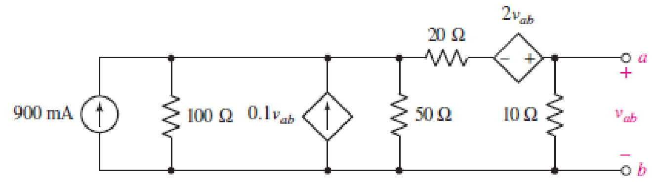
FIGURE 5.94
Expert Solution & Answer
Want to see the full answer?
Check out a sample textbook solution
Students have asked these similar questions
In figure 5.1 of Experiment # 5, what is the computed value of RTH? Show the complete solution.
752
1502
A
5V
2202
4702
B
RTH
Blank 1 0 (type your answer with 2 decimal places)
How would you improve this circuit? Draw a diagram
Q5. Given is a 50 µA, 4 kfi meter. Find the values of R1, R2, R3 in the circuit shown
below so as to give an ammeter with ranges of 200 µA, 1 mA and 20 mA.
[Ans: 1600 fi, 380 fi, 19 fi]
50 μΑ
4 kfi
R1
R2
R3
20 mA
1 mA
200 μΑ
Figure Q5
Chapter 5 Solutions
Loose Leaf for Engineering Circuit Analysis Format: Loose-leaf
Ch. 5.1 - For the circuit of Fig. 5.4, use superposition to...Ch. 5.2 - For the circuit of Fig. 5.7, use superposition to...Ch. 5.2 - For the circuit of Fig. 5.18, compute the current...Ch. 5.2 - For the circuit of Fig. 5.20, compute the voltage...Ch. 5.3 - Using repeated source transformations, determine...Ch. 5.3 - Use Thvenins theorem to find the current through...Ch. 5.3 - Determine the Thvenin and Norton equivalents of...Ch. 5.3 - Find the Thvenin equivalent for the network of...Ch. 5.3 - Find the Thvenin equivalent for the network of...Ch. 5.4 - Consider the circuit of Fig. 5.43. FIGURE 5.43...
Ch. 5.5 - Prob. 11PCh. 5 - Linear systems are so easy to work with that...Ch. 5 - Prob. 2ECh. 5 - Prob. 3ECh. 5 - (a) Employ superposition to determine the current...Ch. 5 - (a) Using superposition to consider each source...Ch. 5 - (a) Determine the individual contributions of each...Ch. 5 - (a) Determine the individual contributions of each...Ch. 5 - After studying the circuit of Fig. 5.53, change...Ch. 5 - Consider the three circuits shown in Fig. 5.54....Ch. 5 - (a) Using superposition, determine the voltage...Ch. 5 - Employ superposition principles to obtain a value...Ch. 5 - (a) Employ superposition to determine the...Ch. 5 - Perform an appropriate source transformation on...Ch. 5 - (a) For the circuit of Fig. 5.59, plot iL versus...Ch. 5 - Determine the current labeled I in the circuit of...Ch. 5 - Verify that the power absorbed by the 7 resistor...Ch. 5 - (a) Determine the current labeled i in the circuit...Ch. 5 - (a) Using repeated source transformations, reduce...Ch. 5 - Prob. 19ECh. 5 - (a) Making use of repeated source transformations,...Ch. 5 - Prob. 21ECh. 5 - (a) With the assistance of source transformations,...Ch. 5 - For the circuit in Fig. 5.67 transform all...Ch. 5 - Prob. 24ECh. 5 - (a) Referring to Fig. 5.69, determine the Thevenin...Ch. 5 - (a) With respect to the circuit depicted in Fig....Ch. 5 - (a) Obtain the Norton equivalent of the network...Ch. 5 - (a) Determine the Thevenin equivalent of the...Ch. 5 - Referring to the circuit of Fig. 5.71: (a)...Ch. 5 - Prob. 30ECh. 5 - (a) Employ Thvenins theorem to obtain a...Ch. 5 - Prob. 32ECh. 5 - Determine the Norton equivalent of the circuit...Ch. 5 - For the circuit of Fig. 5.75: (a) Employ Nortons...Ch. 5 - (a) Obtain a value for the Thvenin equivalent...Ch. 5 - Prob. 36ECh. 5 - Obtain a value for the Thvenin equivalent...Ch. 5 - With regard to the network depicted in Fig. 5.79,...Ch. 5 - Determine the Thvenin and Norton equivalents of...Ch. 5 - Determine the Norton equivalent of the circuit...Ch. 5 - Prob. 41ECh. 5 - Determine the Thvenin and Norton equivalents of...Ch. 5 - Prob. 43ECh. 5 - Prob. 44ECh. 5 - Prob. 45ECh. 5 - (a) For the simple circuit of Fig. 5.87, find the...Ch. 5 - For the circuit drawn in Fig. 5.88, (a) determine...Ch. 5 - Study the circuit of Fig. 5.89. (a) Determine the...Ch. 5 - Prob. 49ECh. 5 - Prob. 50ECh. 5 - With reference to the circuit of Fig. 5.91, (a)...Ch. 5 - Prob. 52ECh. 5 - Select a value for RL in Fig. 5.93 such that it...Ch. 5 - Determine what value of resistance would absorb...Ch. 5 - Derive the equations required to convert from a...Ch. 5 - Convert the - (or "-") connected networks in Fig....Ch. 5 - Convert the Y-(or T-) connected networks in Fig....Ch. 5 - For the network of Fig. 5.97, select a value of R...Ch. 5 - For the network of Fig. 5.98, select a value of R...Ch. 5 - Prob. 60ECh. 5 - Calculate Rin as indicated in Fig.5.100. FIGURE...Ch. 5 - Employ Y conversion techniques as appropriate to...Ch. 5 - Prob. 63ECh. 5 - (a) Use appropriate techniques to obtain both the...Ch. 5 - (a) For the network in Fig. 5.104, replace the...Ch. 5 - Prob. 66ECh. 5 - Prob. 67ECh. 5 - A 2.57 load is connected between terminals a and...Ch. 5 - A load resistor is connected across the open...Ch. 5 - A backup is required for the circuit depicted in...Ch. 5 - (a) Explain in general terms how source...Ch. 5 - The load resistor in Fig. 5.108 can safely...Ch. 5 - Prob. 74ECh. 5 - As part of a security system, a very thin 100 ...Ch. 5 - With respect to the circuit in Fig. 5.90, (a)...
Knowledge Booster


Learn more about
Need a deep-dive on the concept behind this application? Look no further. Learn more about this topic, electrical-engineering and related others by exploring similar questions and additional content below.Similar questions
- 0.2 A moving coil instrument gives a half scale deflection for a current of 20 mA with a potential difference of 300 mV across it. Using direct method, calculate and design: i) Shunt resistors are required to use it as an ammeter to get ranges 0 – 50 A and 0- 100 A. ii) Multiplier resistors are required to use it as a voltmeter of ranges 0 – 150 V and 0– 300 v.arrow_forward0.2 A moving coil instrument gives a half scale deflection for a current of 20 mA with a potentiar difference of 300 mV across it. Using direct method, calculate and design: i) Shunt resistors are required to use it as an ammeter to get ranges 0-50 A and 0- 100 A. ii) Multiplier resistors are required to use it as a voltmeter of ranges 0- 150 V and 0- 300 V.arrow_forward3kQ 1kQ 2kQ 5kQ 6V =1.5V Explain how Kirchhoff's Current Law applies to the central extraordinary node (connecting the 1kQ, 2kQ, and 5kQ Ohm resistors). Use numerical values to prove the validity of the law.arrow_forward
- For the circuit shown in figure 5, make use of superposition as solution method. 5.1) Calculate the voltage in volts at node V0 when the 3 V source is deactivated. 5.2) Calculate the voltage in volts at node V0 when the 9 V source is deactivated. 5.3) Calculate the final voltage V0 in volts for the circuit.arrow_forwardThe terminal voltage of a battery is 13.5 v when 5 A current enters its positive terminal, but when a 5 A current leaves its positive terminal, the terminal voltage becomes 11.5 v. Determine the emf and internal resistance of this battery.arrow_forwardA practical battery has an internal resistance of 0.2 ohm. If this practical battery provides a power of 25 watts to a load with resistance 10 ohms, find 1. the terminal voltage across the battery if it were to be disconnected from the circuitarrow_forward
- A moving coil instrument gives full scale deflection with 15 mA. The resistance of coil is 5 Q. It is desired to convert this instrument into an ammeter to read up to 2 A. How to convert this instrument to read up to 30 V?arrow_forwardANSWER IN ESSAY FORM What is the purpose of Multisim in terms of circuit creation in relation to Ohms law, and what is the significance of Ohms law in our daily lives?arrow_forward5-A) Justify the reason, why the true value of a circuit is suddenly changed into a reduced measured value in a meter while measuring the true value. Mention how it will affect the measurement in the ammeter with necessary drawings. Also, how to reduce the effectarrow_forward
- Switch PROBLEM 5: R Given the circuit: 10 15 V L 1H 6. If the switch is closed, how low will it take for the circuit current to reach maximum? Assume that the initial current is OA. A. 2 sec B. 6 sec C. 5 sec D. 4 secarrow_forward5. Manufacturers recommend always powering devices using batteries of the same brand and freshness. This is important. Batteries change voltage as they discharge, which can cause old batteries to drag down new ones. To illustrate this, consider the circuit shown below. Show that when the load is connected, most of the current that leaves the new battery does not go through the load. IntRes2 200mQ DeadChemistry 1.1V Old Battery IntRes1 100mQ FreshChemistry 1.5V NewBattery Off Von LoadCircuits 1000arrow_forwardThe source voltage of the cell phone battery is 5.34 V. When a current of 0.29 A is taken from the battery, the value of the terminal voltage is 5.17 V. Determine a) the internal resistance of the battery, b) the power supplied by the battery to the circuit and c) the thermal power of the battery (power of the internal resistance) .arrow_forward
arrow_back_ios
SEE MORE QUESTIONS
arrow_forward_ios
Recommended textbooks for you
 Introductory Circuit Analysis (13th Edition)Electrical EngineeringISBN:9780133923605Author:Robert L. BoylestadPublisher:PEARSON
 Delmar's Standard Textbook Of ElectricityElectrical EngineeringISBN:9781337900348Author:Stephen L. HermanPublisher:Cengage Learning
 Programmable Logic ControllersElectrical EngineeringISBN:9780073373843Author:Frank D. PetruzellaPublisher:McGraw-Hill Education
 Fundamentals of Electric CircuitsElectrical EngineeringISBN:9780078028229Author:Charles K Alexander, Matthew SadikuPublisher:McGraw-Hill Education
 Electric Circuits. (11th Edition)Electrical EngineeringISBN:9780134746968Author:James W. Nilsson, Susan RiedelPublisher:PEARSON
 Engineering ElectromagneticsElectrical EngineeringISBN:9780078028151Author:Hayt, William H. (william Hart), Jr, BUCK, John A.Publisher:Mcgraw-hill Education,
Introductory Circuit Analysis (13th Edition)
Electrical Engineering
ISBN:9780133923605
Author:Robert L. Boylestad
Publisher:PEARSON
Delmar's Standard Textbook Of Electricity
Electrical Engineering
ISBN:9781337900348
Author:Stephen L. Herman
Publisher:Cengage Learning
Programmable Logic Controllers
Electrical Engineering
ISBN:9780073373843
Author:Frank D. Petruzella
Publisher:McGraw-Hill Education
Fundamentals of Electric Circuits
Electrical Engineering
ISBN:9780078028229
Author:Charles K Alexander, Matthew Sadiku
Publisher:McGraw-Hill Education
Electric Circuits. (11th Edition)
Electrical Engineering
ISBN:9780134746968
Author:James W. Nilsson, Susan Riedel
Publisher:PEARSON
Engineering Electromagnetics
Electrical Engineering
ISBN:9780078028151
Author:Hayt, William H. (william Hart), Jr, BUCK, John A.
Publisher:Mcgraw-hill Education,
Current Divider Rule; Author: Neso Academy;https://www.youtube.com/watch?v=hRU1mKWUehY;License: Standard YouTube License, CC-BY