
Loose Leaf for Engineering Circuit Analysis Format: Loose-leaf
9th Edition
ISBN: 9781259989452
Author: Hayt
Publisher: Mcgraw Hill Publishers
expand_more
expand_more
format_list_bulleted
Videos
Textbook Question
Chapter 15.2, Problem 4P
Draw the Bode phase plot for the transfer function of Example 15.2.
EXAMPLE 15.2
Obtain the Bode plot of the input impedance of the network shown in Fig. 15.4.
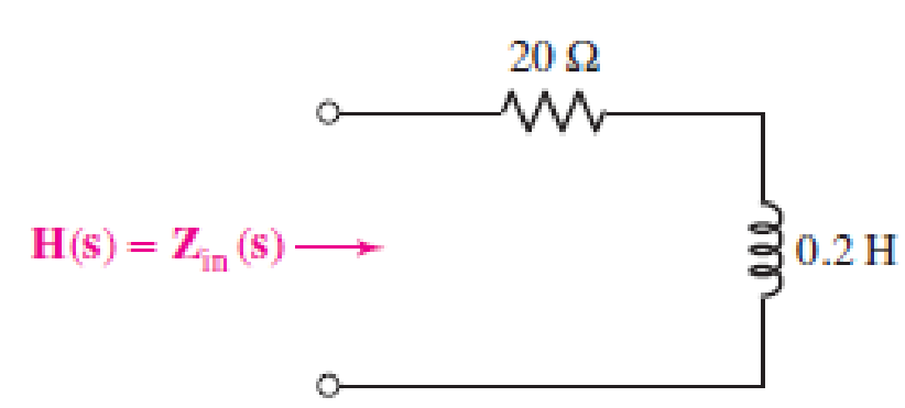
■ FIGURE 15.4
Expert Solution & Answer
Want to see the full answer?
Check out a sample textbook solution
Students have asked these similar questions
+
Vin (1)
-
0.1 F
1 ΚΩ
Vout (t)
Ⓒ
1. A series RLC circuit has a Q of 75 and a pass band between half-power frequencies of 160 cps. Calculate the frequency of resonance and upper and lower frequencies of the pass band.
2. A 15.9 uF capacitor and a 15.1 mH inductor are connected in parallel. In series with these units are a variable resistor R and an adjustable device X, joined in series. (a) Determine the kind and size of device X (inductance in Henry or capacitance in Farad) when the circuit is connected to a 50 volt 400 cps source and is adjusted to resonance. (b) For the resonant condition, calculate the value of R if the voltage drop across the paralleled units is to be 100 volts.
3. An impedance coil having a resistance of 30 ohms and a 50 cps inductive reactance of 33.3 ohms is connected to a 125 volt 60 cps source. A series circuit consisting of a 20 ohm resistor and a variable capacitor is then connected in parallel with the coil. (a) for what values of capacitance will the circuit be in resonance? (b)…
a) Compute the transfer function T(w), the absolute value, and phase at resonant frequency.
b) What kind of filter is this?
Please answer in typing format please ASAP
Chapter 15 Solutions
Loose Leaf for Engineering Circuit Analysis Format: Loose-leaf
Ch. 15.1 - Write an expression for the transfer function of...Ch. 15.2 - Calculate HdB at = 146 rad/s if H(s) equals (a)...Ch. 15.2 - Prob. 3PCh. 15.2 - Draw the Bode phase plot for the transfer function...Ch. 15.2 - Construct a Bode magnitude plot for H(s) equal to...Ch. 15.2 - Draw the Bode phase plot for H(s) equal to (a)...Ch. 15.2 - Prob. 7PCh. 15.3 - A parallel resonant circuit is composed of the...Ch. 15.3 - Prob. 9PCh. 15.4 - A marginally high-Q parallel resonant circuit has...
Ch. 15.5 - A series resonant circuit has a bandwidth of 100...Ch. 15.6 - Referring to the circuit of Fig. 15.25a, let R1 =...Ch. 15.6 - Prob. 13PCh. 15.6 - Prob. 14PCh. 15.6 - The series combination of 10 and 10 nF is in...Ch. 15.7 - A parallel resonant circuit is defined by C = 0.01...Ch. 15.8 - Design a high-pass filter with a cutoff frequency...Ch. 15.8 - Design a bandpass filter with a low-frequency...Ch. 15.8 - Design a low-pass filter circuit with a gain of 30...Ch. 15 - For the RL circuit in Fig. 15.52, (a) determine...Ch. 15 - For the RL circuit in Fig. 15.52, switch the...Ch. 15 - Examine the series RLC circuit in Fig. 15.53, with...Ch. 15 - For the circuit in Fig. 15.54, (a) derive an...Ch. 15 - For the circuit in Fig. 15.55, (a) derive an...Ch. 15 - For the circuit in Fig. 15.56, (a) determine the...Ch. 15 - For the circuit in Fig. 15.57, (a) determine the...Ch. 15 - Sketch the Bode magnitude and phase plots for the...Ch. 15 - Use the Bode approach to sketch the magnitude of...Ch. 15 - If a particular network is described by transfer...Ch. 15 - Use MATLAB to plot the magnitude and phase Bode...Ch. 15 - Determine the Bode magnitude plot for the...Ch. 15 - Determine the Bode magnitude and phase plot for...Ch. 15 - Prob. 15ECh. 15 - Prob. 16ECh. 15 - For the circuit of Fig. 15.56, construct a...Ch. 15 - Construct a magnitude and phase Bode plot for the...Ch. 15 - For the circuit in Fig. 15.54, use LTspice to...Ch. 15 - For the circuit in Fig. 15.55, use LTspice to...Ch. 15 - Prob. 21ECh. 15 - A certain parallel RLC circuit is built using...Ch. 15 - A parallel RLC network is constructed using R = 5...Ch. 15 - Prob. 24ECh. 15 - Delete the 2 resistor in the network of Fig....Ch. 15 - Delete the 1 resistor in the network of Fig....Ch. 15 - Prob. 28ECh. 15 - Prob. 29ECh. 15 - Prob. 30ECh. 15 - A parallel RLC network is constructed with a 200 H...Ch. 15 - Prob. 32ECh. 15 - A parallel RLC circuit is constructed such that it...Ch. 15 - Prob. 34ECh. 15 - Prob. 35ECh. 15 - An RLC circuit is constructed using R = 5 , L = 20...Ch. 15 - Prob. 37ECh. 15 - Prob. 38ECh. 15 - For the network of Fig. 15.25a, R1 = 100 , R2 =...Ch. 15 - Assuming an operating frequency of 200 rad/s, find...Ch. 15 - Prob. 41ECh. 15 - Prob. 42ECh. 15 - For the circuit shown in Fig. 15.64, the voltage...Ch. 15 - Prob. 44ECh. 15 - Prob. 45ECh. 15 - Prob. 46ECh. 15 - The filter shown in Fig. 15.66a has the response...Ch. 15 - Prob. 48ECh. 15 - Examine the filter for the circuit in Fig. 15.68....Ch. 15 - Examine the filter for the circuit in Fig. 15.69....Ch. 15 - (a)Design a high-pass filter with a corner...Ch. 15 - (a) Design a low-pass filter with a break...Ch. 15 - Prob. 53ECh. 15 - Prob. 54ECh. 15 - Design a low-pass filter characterized by a...Ch. 15 - Prob. 56ECh. 15 - The circuit in Fig. 15.70 is known as a notch...Ch. 15 - (a) Design a two-stage op amp filter circuit with...Ch. 15 - Design a circuit which removes the entire audio...Ch. 15 - Prob. 61ECh. 15 - If a high-pass filter is required having gain of 6...Ch. 15 - (a) Design a second-order high-pass Butterworth...Ch. 15 - Design a fourth-order high-pass Butterworth filter...Ch. 15 - (a) Design a Sallen-Key low-pass filter with a...Ch. 15 - (a) Design a Sallen-Key low-pass filter with a...Ch. 15 - A piezoelectric sensor has an equivalent circuit...Ch. 15 - Design a parallel resonant circuit for an AM radio...Ch. 15 - The network of Fig. 15.72 was implemented as a...Ch. 15 - Determine the effect of component tolerance on the...
Additional Engineering Textbook Solutions
Find more solutions based on key concepts
How many coulombs do 93.8 1016 electrons represent?
Principles Of Electric Circuits
Identify the type of input and output configuration for each diff-amp in Figure 18-35.
Electronics Fundamentals: Circuits, Devices & Applications
The current source in the circuit shown generates the current pulse
Find (a) v (0); (b) the instant of time gr...
Electric Circuits. (11th Edition)
A constant voltage of 10V is applied to a 50H inductance, as shown in Figure P3.51 Figure P3 51 The current in ...
Electrical Engineering: Principles & Applications (7th Edition)
Find I0 and I1 in the circuit in Fig.P2.12.
Basic Engineering Circuit Analysis
Explain the main function of each of the following major components of a PLC: a. Processor module (CPU) b. I/O ...
Programmable Logic Controllers
Knowledge Booster


Learn more about
Need a deep-dive on the concept behind this application? Look no further. Learn more about this topic, electrical-engineering and related others by exploring similar questions and additional content below.Similar questions
- Answer Five Questions only. Q1) Obtain the transfer function- for the system shown in figure (1). R. www. Figure (1)arrow_forwardHelp plz: Design a Wein bridge oscillator to generate a sinusoidal waveform of frequency 5KHz.arrow_forward1. A parallel R-L-C circuit is fed by a constant current source of variable frequency. The circuit resonates at 100 kHz and the Q-factor measured at this frequency is 5. Find the frequencies at which the amplitude of the voltage across the circuit falls to (a) 70.7% (b) 50% of the resonant frequency amplitude. [(a) 90.5 kHz ; 110.5 kHz (b) 84.18 kHz ; 118.8 kHz]arrow_forward
- Solve for the following a.) Resonant Frequency b.) total impedance at resonant frequency c.) total power @ resonant frequency with Vs = 1 <0 degrees, (Vrms)arrow_forwardAn R–L–C series circuit has a resonant frequency of 1.2 kHz and a Q-factor at resonance of 30. If the impedance of the circuit at resonance is 50 ohm determine the values of the inductance, and the capacitance. Also find the bandwidth, the lower and upper half-power frequencies and the value of the circuit impedance at the half-power frequencies.arrow_forwardSolve Q5 only 4) A block diagram of an Armstrong FM transmitter is shown in the following figure. The parameters are as follows: fi = 200k H z, fLo = 10.8MHZ, Afi = 25HZ, n1 = 64, n2 = 48: Frequency Multiplier Frequency Multiplier x n2 m(t) NBFM → x(t) f,Af1 fLo 5) The center frequency at the output for Q4 will be: а. 23.6 МHz, 2 MHz b. 1132.8 MHz, 96 MHz c. 12.8 MHz, 9.6 MHz d. None of thesearrow_forward
- Find the transfer function of the elelctrical system. Show complete solution and formula used.arrow_forwardA 15.9-uF capacitor and a 15.1-mH inductor are connected in parallel. In series with these units are a variable resistor R and an adjustable reactive device X. joined inseries. (a) Determine the kind and size of device X inductance in henrys orcapacitance in μF) when the circuit is connected to a 50-volf 400-cycle source and is adjusted to resonance. (b) For the resonant condition calculate the value of R if the voltage drop across the paralleled units is to be 100 V.arrow_forwardAn RLC circuit of 20 ohms resistor, 10 µF capacitor and 5 mH inductor connected to a sinusoidal AC supply of adjustable frequency of default value 2 kHz, at resonance. a) The magnitude of the circuit impedance is 73.561 ohms | b) The circuit impedance is of a capacitive nature 1C) The gupply frequency is 4.4721 kHz O d) The magnitude of the circuit impedance is 20 ohmsarrow_forward
- Problem 15.12 The voltage transfer function for either high-pass prototype filter shown in following figure is H(s) = Either circuit is scaled in both magnitude and s+1 frequency. (Figure 1) Figure + V₂ ● + V₁ C=1F HE R 10 R=10 v₂ (a) + 3L=1H V (b) 1 of 1 Part A Find the scaled transfer function H' (s) for the high-pass prototype filter shown in figure (a). Express your answer in terms of the variables s and kf. H' (s) = Submit Part B H' (s) = Submit VAΣo↓vec ΑΣΦΑ Find the scaled transfer function H' (s) for the high-pass prototype filter shown in figure (b). Express your answer in terms of the variables s and kf. 15. ΑΣΦΑ Provide Feedback Request Answer Request Answer vec P Pearson ? wwwww F ?arrow_forwardDerive and plot the magnitude and phase responses of the first order difference system, y[n] = x[n]–x[n − 1]. ..arrow_forwardV:OV 3G !!.: Classroom > docs.google.com • * الاسم الرباعي الكامل Your answer Engineering and Numerical Analysis Lecture: Safa Al-waily 01| plot the Amplidude s phase spectyum (signal & double side) Q2 |Fimd x plot h complex form of (Fis) for he fenetion. Scanned by TapScanner 1 Add file Submit Clear form Never submit passwords through Google Forms. + •.. 5arrow_forward
arrow_back_ios
SEE MORE QUESTIONS
arrow_forward_ios
Recommended textbooks for you
 Introductory Circuit Analysis (13th Edition)Electrical EngineeringISBN:9780133923605Author:Robert L. BoylestadPublisher:PEARSON
 Delmar's Standard Textbook Of ElectricityElectrical EngineeringISBN:9781337900348Author:Stephen L. HermanPublisher:Cengage Learning
 Programmable Logic ControllersElectrical EngineeringISBN:9780073373843Author:Frank D. PetruzellaPublisher:McGraw-Hill Education
 Fundamentals of Electric CircuitsElectrical EngineeringISBN:9780078028229Author:Charles K Alexander, Matthew SadikuPublisher:McGraw-Hill Education
 Electric Circuits. (11th Edition)Electrical EngineeringISBN:9780134746968Author:James W. Nilsson, Susan RiedelPublisher:PEARSON
 Engineering ElectromagneticsElectrical EngineeringISBN:9780078028151Author:Hayt, William H. (william Hart), Jr, BUCK, John A.Publisher:Mcgraw-hill Education,
Introductory Circuit Analysis (13th Edition)
Electrical Engineering
ISBN:9780133923605
Author:Robert L. Boylestad
Publisher:PEARSON
Delmar's Standard Textbook Of Electricity
Electrical Engineering
ISBN:9781337900348
Author:Stephen L. Herman
Publisher:Cengage Learning
Programmable Logic Controllers
Electrical Engineering
ISBN:9780073373843
Author:Frank D. Petruzella
Publisher:McGraw-Hill Education
Fundamentals of Electric Circuits
Electrical Engineering
ISBN:9780078028229
Author:Charles K Alexander, Matthew Sadiku
Publisher:McGraw-Hill Education
Electric Circuits. (11th Edition)
Electrical Engineering
ISBN:9780134746968
Author:James W. Nilsson, Susan Riedel
Publisher:PEARSON
Engineering Electromagnetics
Electrical Engineering
ISBN:9780078028151
Author:Hayt, William H. (william Hart), Jr, BUCK, John A.
Publisher:Mcgraw-hill Education,
Resonance Circuits: LC Inductor-Capacitor Resonating Circuits; Author: Physics Videos by Eugene Khutoryansky;https://www.youtube.com/watch?v=Mq-PF1vo9QA;License: Standard YouTube License, CC-BY