
Loose Leaf for Engineering Circuit Analysis Format: Loose-leaf
9th Edition
ISBN: 9781259989452
Author: Hayt
Publisher: Mcgraw Hill Publishers
expand_more
expand_more
format_list_bulleted
Videos
Textbook Question
Chapter 15, Problem 18E
Construct a magnitude and phase Bode plot for the transfer function H(s) = Vout/Vin for the circuit shown in Fig. 15.57 and circuit values of R1 = R2 = 2 kΩ, R3 = 20 kΩ, and L1 = L2 = 2H.
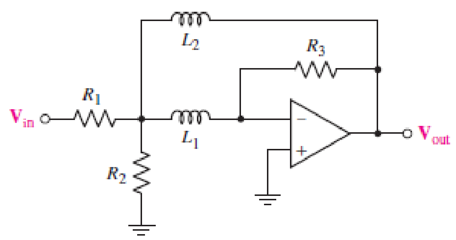
■ FIGURE 15.57
Expert Solution & Answer
Want to see the full answer?
Check out a sample textbook solution
Students have asked these similar questions
Design a Passive RL based Band Pass filter for specific bandwidth. A filter which allows the signals which have frequencies in the range of 80 Hz to 800 Hz.
1. A series RLC circuit has a Q of 75 and a pass band between half-power frequencies of 160 cps. Calculate the frequency of resonance and upper and lower frequencies of the pass band.
2. A 15.9 uF capacitor and a 15.1 mH inductor are connected in parallel. In series with these units are a variable resistor R and an adjustable device X, joined in series. (a) Determine the kind and size of device X (inductance in Henry or capacitance in Farad) when the circuit is connected to a 50 volt 400 cps source and is adjusted to resonance. (b) For the resonant condition, calculate the value of R if the voltage drop across the paralleled units is to be 100 volts.
3. An impedance coil having a resistance of 30 ohms and a 50 cps inductive reactance of 33.3 ohms is connected to a 125 volt 60 cps source. A series circuit consisting of a 20 ohm resistor and a variable capacitor is then connected in parallel with the coil. (a) for what values of capacitance will the circuit be in resonance? (b)…
4.
The Bode plot shown below represents the voltage gain of a particular amplifier. Sketch the input and output waveforms, v,() and
v(1) if the input to the amplifier is v, (1) = 10 + 10cos(400t + 60°) mV. Use the graph paper on the next page for your sketches and
label the minimum and maximum value for each waveform.
60
Bode Diagram
58
56
54
52
50
48
46
44
42
40
-5
-10
-15
-20
-25
-30
-35
-40
-45
-50
-55
-60
100
101
102
Frequency (rad/s)
10
104
105
(Bap) aseud
Magnitude (dB)
Chapter 15 Solutions
Loose Leaf for Engineering Circuit Analysis Format: Loose-leaf
Ch. 15.1 - Write an expression for the transfer function of...Ch. 15.2 - Calculate HdB at = 146 rad/s if H(s) equals (a)...Ch. 15.2 - Prob. 3PCh. 15.2 - Draw the Bode phase plot for the transfer function...Ch. 15.2 - Construct a Bode magnitude plot for H(s) equal to...Ch. 15.2 - Draw the Bode phase plot for H(s) equal to (a)...Ch. 15.2 - Prob. 7PCh. 15.3 - A parallel resonant circuit is composed of the...Ch. 15.3 - Prob. 9PCh. 15.4 - A marginally high-Q parallel resonant circuit has...
Ch. 15.5 - A series resonant circuit has a bandwidth of 100...Ch. 15.6 - Referring to the circuit of Fig. 15.25a, let R1 =...Ch. 15.6 - Prob. 13PCh. 15.6 - Prob. 14PCh. 15.6 - The series combination of 10 and 10 nF is in...Ch. 15.7 - A parallel resonant circuit is defined by C = 0.01...Ch. 15.8 - Design a high-pass filter with a cutoff frequency...Ch. 15.8 - Design a bandpass filter with a low-frequency...Ch. 15.8 - Design a low-pass filter circuit with a gain of 30...Ch. 15 - For the RL circuit in Fig. 15.52, (a) determine...Ch. 15 - For the RL circuit in Fig. 15.52, switch the...Ch. 15 - Examine the series RLC circuit in Fig. 15.53, with...Ch. 15 - For the circuit in Fig. 15.54, (a) derive an...Ch. 15 - For the circuit in Fig. 15.55, (a) derive an...Ch. 15 - For the circuit in Fig. 15.56, (a) determine the...Ch. 15 - For the circuit in Fig. 15.57, (a) determine the...Ch. 15 - Sketch the Bode magnitude and phase plots for the...Ch. 15 - Use the Bode approach to sketch the magnitude of...Ch. 15 - If a particular network is described by transfer...Ch. 15 - Use MATLAB to plot the magnitude and phase Bode...Ch. 15 - Determine the Bode magnitude plot for the...Ch. 15 - Determine the Bode magnitude and phase plot for...Ch. 15 - Prob. 15ECh. 15 - Prob. 16ECh. 15 - For the circuit of Fig. 15.56, construct a...Ch. 15 - Construct a magnitude and phase Bode plot for the...Ch. 15 - For the circuit in Fig. 15.54, use LTspice to...Ch. 15 - For the circuit in Fig. 15.55, use LTspice to...Ch. 15 - Prob. 21ECh. 15 - A certain parallel RLC circuit is built using...Ch. 15 - A parallel RLC network is constructed using R = 5...Ch. 15 - Prob. 24ECh. 15 - Delete the 2 resistor in the network of Fig....Ch. 15 - Delete the 1 resistor in the network of Fig....Ch. 15 - Prob. 28ECh. 15 - Prob. 29ECh. 15 - Prob. 30ECh. 15 - A parallel RLC network is constructed with a 200 H...Ch. 15 - Prob. 32ECh. 15 - A parallel RLC circuit is constructed such that it...Ch. 15 - Prob. 34ECh. 15 - Prob. 35ECh. 15 - An RLC circuit is constructed using R = 5 , L = 20...Ch. 15 - Prob. 37ECh. 15 - Prob. 38ECh. 15 - For the network of Fig. 15.25a, R1 = 100 , R2 =...Ch. 15 - Assuming an operating frequency of 200 rad/s, find...Ch. 15 - Prob. 41ECh. 15 - Prob. 42ECh. 15 - For the circuit shown in Fig. 15.64, the voltage...Ch. 15 - Prob. 44ECh. 15 - Prob. 45ECh. 15 - Prob. 46ECh. 15 - The filter shown in Fig. 15.66a has the response...Ch. 15 - Prob. 48ECh. 15 - Examine the filter for the circuit in Fig. 15.68....Ch. 15 - Examine the filter for the circuit in Fig. 15.69....Ch. 15 - (a)Design a high-pass filter with a corner...Ch. 15 - (a) Design a low-pass filter with a break...Ch. 15 - Prob. 53ECh. 15 - Prob. 54ECh. 15 - Design a low-pass filter characterized by a...Ch. 15 - Prob. 56ECh. 15 - The circuit in Fig. 15.70 is known as a notch...Ch. 15 - (a) Design a two-stage op amp filter circuit with...Ch. 15 - Design a circuit which removes the entire audio...Ch. 15 - Prob. 61ECh. 15 - If a high-pass filter is required having gain of 6...Ch. 15 - (a) Design a second-order high-pass Butterworth...Ch. 15 - Design a fourth-order high-pass Butterworth filter...Ch. 15 - (a) Design a Sallen-Key low-pass filter with a...Ch. 15 - (a) Design a Sallen-Key low-pass filter with a...Ch. 15 - A piezoelectric sensor has an equivalent circuit...Ch. 15 - Design a parallel resonant circuit for an AM radio...Ch. 15 - The network of Fig. 15.72 was implemented as a...Ch. 15 - Determine the effect of component tolerance on the...
Additional Engineering Textbook Solutions
Find more solutions based on key concepts
Does the severity of an electric shock increase ordecrease with eh of the following changes? a. A decrease in t...
Electric Motors and Control Systems
How many coulombs do 93.8 1016 electrons represent?
Principles Of Electric Circuits
The voltage source of the circuit shown in Fig. P1.29 is given by s(t)=25cos(4104t45)(V). Obtain an expression ...
Fundamentals of Applied Electromagnetics (7th Edition)
Identify the type of input and output configuration for each diff-amp in Figure 18-35.
Electronics Fundamentals: Circuits, Devices & Applications
Explain the main function of each of the following major components of a PLC: a. Processor module (CPU) b. I/O ...
Programmable Logic Controllers
Electric power systems provide energy in a variety of commercial and industrial settings. Make a list of system...
Principles and Applications of Electrical Engineering
Knowledge Booster


Learn more about
Need a deep-dive on the concept behind this application? Look no further. Learn more about this topic, electrical-engineering and related others by exploring similar questions and additional content below.Similar questions
- Problem 4: Consider the electrical circuit depicted in the figure below. Vin L Vout 1. Compute the transfer function G(jw) = Dout(jw) Vin (jw) 2. Draw its Bode magnitude plot and based on the shape of the plot explain the characteristic of the circuit above. What is the name of this circuit? 3. Assuming that L= 30 mH, compute the value of the resistor R such that cutoff frequency of the circuit above is 200 kHz.arrow_forward1. A parallel R-L-C circuit is fed by a constant current source of variable frequency. The circuit resonates at 100 kHz and the Q-factor measured at this frequency is 5. Find the frequencies at which the amplitude of the voltage across the circuit falls to (a) 70.7% (b) 50% of the resonant frequency amplitude. [(a) 90.5 kHz ; 110.5 kHz (b) 84.18 kHz ; 118.8 kHz]arrow_forwardFor the OP-Amp circuit below: a) Derive the transfer function, T(s). b) Calculate the magnitude of the filter. c) What is the order of this filter? d) What type of filter is this? e) Draw the S-Plane Singularities shown the radial distance from the origin. 8Ω V10 O v2 1/16 F 40arrow_forward
- I want the answer in detail and as quickly as possible please Q/ Using capacitors and resistors, design A - (band-pass filters) with Fl=108HZ and Fh=112HZ. B - Design (band-pass filters) with Fl = 218HZ and Fh = 223HZ. %3D ((And make sure that the values are available in the market))arrow_forwardVS+ -SA V1 5 V2 5 .ac dec 100 1 1Meg lib LM741.mod VIN V3 R1 C1 1.3k 0.12μ AC 1 Figure. Active Band Pass Filter R2 1.3k C2 0.12μ Imax -VS+ -SA U1 VOUT LM741/NS Provide the following expressions or values as required: VOUT VIN ) Expression for the maximum gain/magnitude G = ) Expression for the natural frequency fo and its corresponding value ) Expression for selectivity Q and its corresponding value and its corresponding valuearrow_forwardIn the following figure, R=9kΩ ad Cf=3nF. Vin(t)=5sin(2pi*10khz*t) draw the output waveform Vin and Vo and derive the expression of the Vo(t) as a function of time & Vo(f) as a function of varying signal frequency.arrow_forward
- (a) Find the transfer function for the circuit shown in Figure Q.2a if the input voltage is Fs) and the output voltage is capacitor voltage Vs). 20 2F HH 10 (1) Figure Q2a IH 40arrow_forwardProblem Solving Coverage: BJT Small Signal Analysis Instruction: WRITE the complete solutions and box your final answer. Use three (3) decimal places in your final answer. For the figure below: H 6.8 µF www ww 16 k2 16 2.2kQ 4. Solve the value of Zi, Zo, Av and Ai 6.8 µF HH 3-100 0.75 k 10µF Determine the following: A. DC Analysis: Determine the value of IE and VCE B. AC Analysis: 1. Draw/sketch the AC Equivalent Circuit using re model 2. Solve for re 3. Derive the equation of Zi, Zo, Av and Ai 5.6 karrow_forward1. A tuned circuit has a resonant frequency of 18 MHz and a bandwidth of 120 kHz. What are the upper and lower cutoff frequencies?2. What value of Q is needed to achieve a bandwidth of 4 kHz at 3.6 MHz?3. A filter has a 6-dB bandwidth of 3500 Hz and a 60-dB bandwidth of 8400 Hz. What is the shape factor?arrow_forward
- Design a bandpass filter for a graphic equalizer to provide an amplification of2 within the band of frequencies between 100 and 10,000 Hz. Use 0.2 μFcapacitors.arrow_forwardPassive filters are made of passive components, tuned to the harmonic frequencies that are to be attenuated. Show that a series LR circuit is a lowpass filter if the output is taken across the resistor.arrow_forwardDiscussions: 1) For the following filter, 0.15pF Vout Vin 3300 2) Explain what a band-pass filter is, and how it differs from either a low-pass or a high-pass filter circuit. Also, explain what a band-stop filter is, and draw Bode plots representative of both band-pass and band-stop filter types.arrow_forward
arrow_back_ios
SEE MORE QUESTIONS
arrow_forward_ios
Recommended textbooks for you
 Introductory Circuit Analysis (13th Edition)Electrical EngineeringISBN:9780133923605Author:Robert L. BoylestadPublisher:PEARSON
 Delmar's Standard Textbook Of ElectricityElectrical EngineeringISBN:9781337900348Author:Stephen L. HermanPublisher:Cengage Learning
 Programmable Logic ControllersElectrical EngineeringISBN:9780073373843Author:Frank D. PetruzellaPublisher:McGraw-Hill Education
 Fundamentals of Electric CircuitsElectrical EngineeringISBN:9780078028229Author:Charles K Alexander, Matthew SadikuPublisher:McGraw-Hill Education
 Electric Circuits. (11th Edition)Electrical EngineeringISBN:9780134746968Author:James W. Nilsson, Susan RiedelPublisher:PEARSON
 Engineering ElectromagneticsElectrical EngineeringISBN:9780078028151Author:Hayt, William H. (william Hart), Jr, BUCK, John A.Publisher:Mcgraw-hill Education,
Introductory Circuit Analysis (13th Edition)
Electrical Engineering
ISBN:9780133923605
Author:Robert L. Boylestad
Publisher:PEARSON
Delmar's Standard Textbook Of Electricity
Electrical Engineering
ISBN:9781337900348
Author:Stephen L. Herman
Publisher:Cengage Learning
Programmable Logic Controllers
Electrical Engineering
ISBN:9780073373843
Author:Frank D. Petruzella
Publisher:McGraw-Hill Education
Fundamentals of Electric Circuits
Electrical Engineering
ISBN:9780078028229
Author:Charles K Alexander, Matthew Sadiku
Publisher:McGraw-Hill Education
Electric Circuits. (11th Edition)
Electrical Engineering
ISBN:9780134746968
Author:James W. Nilsson, Susan Riedel
Publisher:PEARSON
Engineering Electromagnetics
Electrical Engineering
ISBN:9780078028151
Author:Hayt, William H. (william Hart), Jr, BUCK, John A.
Publisher:Mcgraw-hill Education,
Resonance Circuits: LC Inductor-Capacitor Resonating Circuits; Author: Physics Videos by Eugene Khutoryansky;https://www.youtube.com/watch?v=Mq-PF1vo9QA;License: Standard YouTube License, CC-BY