
Loose Leaf for Engineering Circuit Analysis Format: Loose-leaf
9th Edition
ISBN: 9781259989452
Author: Hayt
Publisher: Mcgraw Hill Publishers
expand_more
expand_more
format_list_bulleted
Videos
Textbook Question
Chapter 15, Problem 20E
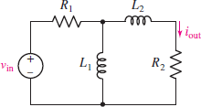
For the circuit in Fig. 15.55, use LTspice to construct a Bode plot of the frequency response for the case where R1 = 3 kΩ, R2 = 12 kΩ, L1 = 5 mH, and L2 = 8 mH. Use your plot to estimate locations of poles and zeros.
FIGURE 15.55
Expert Solution & Answer
Want to see the full answer?
Check out a sample textbook solution
Students have asked these similar questions
1. A parallel R-L-C circuit is fed by a constant
current source of variable frequency. The circuit
resonates at 100 kHz and the Q-factor
measured at this frequency is 5. Find the
frequencies at which the amplitude of the
voltage across the circuit falls to (a) 70.7% (b)
50% of the resonant frequency amplitude. [(a)
90.5 kHz ; 110.5 kHz (b) 84.18 kHz ; 118.8 kHz]
21) Looking at the following circuit, select the correct Transfer fucntion.
Please recognize that the answers are expressed in rectangular coordinates
and not in magnitude, making this an easy problem.
21).
ww w
For the circuit in the given figure, assume L = 0.5 H and R= 200 kohm.
ele
O Vout (jw)
Vin (jw)
200 k
Vin
R
Vout
–200 k+jw0.5
Vout (jw)
ju0.5
200 k- jw0.5
Vin (jw)
O Vout (ju)
Vin (jw)
- jw0.5
200 k– jw0.5
Vout (jw)
200 k
Vin (jw)
200 k+jw0.5
Given the series RLC circuit. If R=10 ohm, find the values of L and C such that the network will have a center frequency of 100 kHz and a
bandwidth of 1kHz. The output of the circuit is taken across series LC.
Select one:
O a. 1.59 mH and 1.59 nF
O b. 1.59 mH and 1.59 uF
1.59 H and 1.59 nF
1.59 uH and 1.59 uF
O C.
O d.
Chapter 15 Solutions
Loose Leaf for Engineering Circuit Analysis Format: Loose-leaf
Ch. 15.1 - Write an expression for the transfer function of...Ch. 15.2 - Calculate HdB at = 146 rad/s if H(s) equals (a)...Ch. 15.2 - Prob. 3PCh. 15.2 - Draw the Bode phase plot for the transfer function...Ch. 15.2 - Construct a Bode magnitude plot for H(s) equal to...Ch. 15.2 - Draw the Bode phase plot for H(s) equal to (a)...Ch. 15.2 - Prob. 7PCh. 15.3 - A parallel resonant circuit is composed of the...Ch. 15.3 - Prob. 9PCh. 15.4 - A marginally high-Q parallel resonant circuit has...
Ch. 15.5 - A series resonant circuit has a bandwidth of 100...Ch. 15.6 - Referring to the circuit of Fig. 15.25a, let R1 =...Ch. 15.6 - Prob. 13PCh. 15.6 - Prob. 14PCh. 15.6 - The series combination of 10 and 10 nF is in...Ch. 15.7 - A parallel resonant circuit is defined by C = 0.01...Ch. 15.8 - Design a high-pass filter with a cutoff frequency...Ch. 15.8 - Design a bandpass filter with a low-frequency...Ch. 15.8 - Design a low-pass filter circuit with a gain of 30...Ch. 15 - For the RL circuit in Fig. 15.52, (a) determine...Ch. 15 - For the RL circuit in Fig. 15.52, switch the...Ch. 15 - Examine the series RLC circuit in Fig. 15.53, with...Ch. 15 - For the circuit in Fig. 15.54, (a) derive an...Ch. 15 - For the circuit in Fig. 15.55, (a) derive an...Ch. 15 - For the circuit in Fig. 15.56, (a) determine the...Ch. 15 - For the circuit in Fig. 15.57, (a) determine the...Ch. 15 - Sketch the Bode magnitude and phase plots for the...Ch. 15 - Use the Bode approach to sketch the magnitude of...Ch. 15 - If a particular network is described by transfer...Ch. 15 - Use MATLAB to plot the magnitude and phase Bode...Ch. 15 - Determine the Bode magnitude plot for the...Ch. 15 - Determine the Bode magnitude and phase plot for...Ch. 15 - Prob. 15ECh. 15 - Prob. 16ECh. 15 - For the circuit of Fig. 15.56, construct a...Ch. 15 - Construct a magnitude and phase Bode plot for the...Ch. 15 - For the circuit in Fig. 15.54, use LTspice to...Ch. 15 - For the circuit in Fig. 15.55, use LTspice to...Ch. 15 - Prob. 21ECh. 15 - A certain parallel RLC circuit is built using...Ch. 15 - A parallel RLC network is constructed using R = 5...Ch. 15 - Prob. 24ECh. 15 - Delete the 2 resistor in the network of Fig....Ch. 15 - Delete the 1 resistor in the network of Fig....Ch. 15 - Prob. 28ECh. 15 - Prob. 29ECh. 15 - Prob. 30ECh. 15 - A parallel RLC network is constructed with a 200 H...Ch. 15 - Prob. 32ECh. 15 - A parallel RLC circuit is constructed such that it...Ch. 15 - Prob. 34ECh. 15 - Prob. 35ECh. 15 - An RLC circuit is constructed using R = 5 , L = 20...Ch. 15 - Prob. 37ECh. 15 - Prob. 38ECh. 15 - For the network of Fig. 15.25a, R1 = 100 , R2 =...Ch. 15 - Assuming an operating frequency of 200 rad/s, find...Ch. 15 - Prob. 41ECh. 15 - Prob. 42ECh. 15 - For the circuit shown in Fig. 15.64, the voltage...Ch. 15 - Prob. 44ECh. 15 - Prob. 45ECh. 15 - Prob. 46ECh. 15 - The filter shown in Fig. 15.66a has the response...Ch. 15 - Prob. 48ECh. 15 - Examine the filter for the circuit in Fig. 15.68....Ch. 15 - Examine the filter for the circuit in Fig. 15.69....Ch. 15 - (a)Design a high-pass filter with a corner...Ch. 15 - (a) Design a low-pass filter with a break...Ch. 15 - Prob. 53ECh. 15 - Prob. 54ECh. 15 - Design a low-pass filter characterized by a...Ch. 15 - Prob. 56ECh. 15 - The circuit in Fig. 15.70 is known as a notch...Ch. 15 - (a) Design a two-stage op amp filter circuit with...Ch. 15 - Design a circuit which removes the entire audio...Ch. 15 - Prob. 61ECh. 15 - If a high-pass filter is required having gain of 6...Ch. 15 - (a) Design a second-order high-pass Butterworth...Ch. 15 - Design a fourth-order high-pass Butterworth filter...Ch. 15 - (a) Design a Sallen-Key low-pass filter with a...Ch. 15 - (a) Design a Sallen-Key low-pass filter with a...Ch. 15 - A piezoelectric sensor has an equivalent circuit...Ch. 15 - Design a parallel resonant circuit for an AM radio...Ch. 15 - The network of Fig. 15.72 was implemented as a...Ch. 15 - Determine the effect of component tolerance on the...
Additional Engineering Textbook Solutions
Find more solutions based on key concepts
What is the color code for a 365- five-band precision resistor with a tolerance of 5 percent?
ELECTRICITY FOR TRADES (LOOSELEAF)
Write the nodal equations for the network of Fig. 8.137 using the general approach. Find the nodal voltages usi...
Introductory Circuit Analysis (13th Edition)
Three point charges of equal magnitude q, that will yield a zero net electric field at the origin.
Engineering Electromagnetics
Identify the type of input and output configuration for each diff-amp in Figure 18-35.
Electronics Fundamentals: Circuits, Devices & Applications
Analog Voltmeter Design Figure P2-98(a) shows a voltmeter circuit consisting of a D'Arsonval meter, two series ...
ANALYSIS+DESIGN OF LINEAR CIRCUITS(LL)
Explain the main function of each of the following major components of a PLC: a. Processor module (CPU) b. I/O ...
Programmable Logic Controllers
Knowledge Booster


Learn more about
Need a deep-dive on the concept behind this application? Look no further. Learn more about this topic, electrical-engineering and related others by exploring similar questions and additional content below.Similar questions
- The magnitude and phase diagrams are provided for a passive filter. Input signal vin(t)=15 cos(20000t+100°) V is applied. What is the output voltage in V when t-1ms ? Series RLC H(s) -20 -30 -40 700 10 10 180 150 ... ... ... ... 100 ... 50 10 10 Frequency (rad'sec) Phase (deg) Mag (dB)arrow_forwardProblem Solving Coverage: BJT Small Signal Analysis Instruction: WRITE the complete solutions and box your final answer. Use three (3) decimal places in your final answer. For the figure below: H 6.8 µF Determine the following: B. AC Analysis: www ww 68 kf 16 k2 16 V 2.2kQ 4. Solve the value of Zi, Zo, Av and Ai 2. Solve for re 3. Derive the equation of Zi, Zo, Av and Ai 0.75 k 6.8 µF H 3-100 10 µF 5.6 karrow_forwardPlot the magnitude and phase plot for the following transfer function, use the templates from the class notes module so as to provide somewhat an accurate representation of the magnitude and phase plots. H (ju) 10 jw (0.01jw+1) (0.1jw+1)arrow_forward
- Start by finding the Thévenin equivalent circuit seen by the capacitance. Then, sketch the magnitude of the transfer function H(jw) = Vout/Vin. What is the value of the cutoff frequency?arrow_forwardQ.3/ Find the difference equation that describe, the following digital filter: M (Z) E (2) 27²-3.52 +1.9 2²³²-2.77² +Z-0.95arrow_forwardPassive filters are made of passive components, tuned to the harmonic frequencies that are to be attenuated. Show that a series LR circuit is a lowpass filter if the output is taken across the resistor.arrow_forward
- Consider the following frequency selective circuit. At what frequency, in hertz, will the magnitude of H(jw) equal zero? Given R = 22 , L = 250 mH, C = 10 mF. L C R Voarrow_forwardA series circuit consists of a reactor of 0.1 henry inductance and 5 ohms resistance and a capacitor of 25.5 μ F capacitance. Find the resonance frequency and the percentage change in the current for a divergence of 1 percent from the resonance frequency. [100 Hz, 1.96% at 99 Hz; 4.2% at 101 Hz]arrow_forwardI DOK In the circuit shown in the given figure, determine the frequency response function in the form: V(w) H. (jw)= 1,400) 0 + Vjos) ww R₁ C H 145/(0) 1,0) A R₂ Vjos)arrow_forward
- Ro = 5kQ. Determine the lower cutoff frequency f (in kHz) ? +Vcc MF ZTC 5k2 2.5 mA MF -Vec Assume: be PF а. 1.2 O b. 0.20 c. 16.7 O d. 100arrow_forwardA parallel resonant circuit has a resistance of 2 k2 and half-power frequencies of 86 kHz and 90 kHz. Determine: (a) the capacitance (in nF) (b) the inductance (in uH) (c) the resonant frequency (in krad/s) (d) the bandwidth (in krad/s) (e) the quality factorarrow_forwardA series circuit with R = 10 2, L = 0.1 H and C = %3D %3D %3D 50 µF has an applied voltage V = 50 L0° with a variable frequency. Find the resonant frequency, the value of frequency at which maximum voltage occurs across the inductor and the value of fre- quency at which maximum voltage occurs across the сараcitor.arrow_forward
arrow_back_ios
SEE MORE QUESTIONS
arrow_forward_ios
Recommended textbooks for you
 Introductory Circuit Analysis (13th Edition)Electrical EngineeringISBN:9780133923605Author:Robert L. BoylestadPublisher:PEARSON
 Delmar's Standard Textbook Of ElectricityElectrical EngineeringISBN:9781337900348Author:Stephen L. HermanPublisher:Cengage Learning
 Programmable Logic ControllersElectrical EngineeringISBN:9780073373843Author:Frank D. PetruzellaPublisher:McGraw-Hill Education
 Fundamentals of Electric CircuitsElectrical EngineeringISBN:9780078028229Author:Charles K Alexander, Matthew SadikuPublisher:McGraw-Hill Education
 Electric Circuits. (11th Edition)Electrical EngineeringISBN:9780134746968Author:James W. Nilsson, Susan RiedelPublisher:PEARSON
 Engineering ElectromagneticsElectrical EngineeringISBN:9780078028151Author:Hayt, William H. (william Hart), Jr, BUCK, John A.Publisher:Mcgraw-hill Education,
Introductory Circuit Analysis (13th Edition)
Electrical Engineering
ISBN:9780133923605
Author:Robert L. Boylestad
Publisher:PEARSON
Delmar's Standard Textbook Of Electricity
Electrical Engineering
ISBN:9781337900348
Author:Stephen L. Herman
Publisher:Cengage Learning
Programmable Logic Controllers
Electrical Engineering
ISBN:9780073373843
Author:Frank D. Petruzella
Publisher:McGraw-Hill Education
Fundamentals of Electric Circuits
Electrical Engineering
ISBN:9780078028229
Author:Charles K Alexander, Matthew Sadiku
Publisher:McGraw-Hill Education
Electric Circuits. (11th Edition)
Electrical Engineering
ISBN:9780134746968
Author:James W. Nilsson, Susan Riedel
Publisher:PEARSON
Engineering Electromagnetics
Electrical Engineering
ISBN:9780078028151
Author:Hayt, William H. (william Hart), Jr, BUCK, John A.
Publisher:Mcgraw-hill Education,
David Sarnoff, Howard Armstrong & the Superheterodyne Receiver; Author: Kathy Loves Physics & History;https://www.youtube.com/watch?v=7eTfF67Ka5w;License: Standard Youtube License