
Loose Leaf for Engineering Circuit Analysis Format: Loose-leaf
9th Edition
ISBN: 9781259989452
Author: Hayt
Publisher: Mcgraw Hill Publishers
expand_more
expand_more
format_list_bulleted
Concept explainers
Videos
Textbook Question
Chapter 15, Problem 43E
For the circuit shown in Fig. 15.64, the voltage source has magnitude 1 V and phase angle 0°. Determine the resonant frequency ω0 and the value of Vx at 0.95ω0.
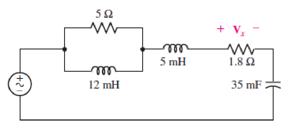
■ FIGURE 15.64
Expert Solution & Answer
Want to see the full answer?
Check out a sample textbook solution
Students have asked these similar questions
A 15.9-uF capacitor and a 15.1-mH inductor are connected in parallel. In series with these units are a variable resistor R and an adjustable reactive device X. joined inseries. (a) Determine the kind and size of device X inductance in henrys orcapacitance in μF) when the circuit is connected to a 50-volf 400-cycle source and is adjusted to resonance. (b) For the resonant condition calculate the value of R if the voltage drop across the paralleled units is to be 100 V.
Q.5:
a) Correct any five of the following sentences using suitable scientific phrases.
1. At any resonant circuit the input impedance is reactance (X or Xc).
2. The locus of inductive load is a vector in the 2nd quadrant.
3. Any non-sinusoidal wave can be represented by a sum of sine waves with harmonic
frequencies.
4. The power dissipated in a resistance is equal to 21'R in non-sinusoidal input signal.
5. In transient circuit when the switch is closed for a long time the inductor behaves as an
open circuit.
6. The DC input voltage could be represented by Vs in Laplace methods.
7. The electrical energy is stored in the resistance.
(15 marks]
Convert to rectangular form: (a) 2Đ15°, (b) 3Đ-10°
a).
b)
Chapter 15 Solutions
Loose Leaf for Engineering Circuit Analysis Format: Loose-leaf
Ch. 15.1 - Write an expression for the transfer function of...Ch. 15.2 - Calculate HdB at = 146 rad/s if H(s) equals (a)...Ch. 15.2 - Prob. 3PCh. 15.2 - Draw the Bode phase plot for the transfer function...Ch. 15.2 - Construct a Bode magnitude plot for H(s) equal to...Ch. 15.2 - Draw the Bode phase plot for H(s) equal to (a)...Ch. 15.2 - Prob. 7PCh. 15.3 - A parallel resonant circuit is composed of the...Ch. 15.3 - Prob. 9PCh. 15.4 - A marginally high-Q parallel resonant circuit has...
Ch. 15.5 - A series resonant circuit has a bandwidth of 100...Ch. 15.6 - Referring to the circuit of Fig. 15.25a, let R1 =...Ch. 15.6 - Prob. 13PCh. 15.6 - Prob. 14PCh. 15.6 - The series combination of 10 and 10 nF is in...Ch. 15.7 - A parallel resonant circuit is defined by C = 0.01...Ch. 15.8 - Design a high-pass filter with a cutoff frequency...Ch. 15.8 - Design a bandpass filter with a low-frequency...Ch. 15.8 - Design a low-pass filter circuit with a gain of 30...Ch. 15 - For the RL circuit in Fig. 15.52, (a) determine...Ch. 15 - For the RL circuit in Fig. 15.52, switch the...Ch. 15 - Examine the series RLC circuit in Fig. 15.53, with...Ch. 15 - For the circuit in Fig. 15.54, (a) derive an...Ch. 15 - For the circuit in Fig. 15.55, (a) derive an...Ch. 15 - For the circuit in Fig. 15.56, (a) determine the...Ch. 15 - For the circuit in Fig. 15.57, (a) determine the...Ch. 15 - Sketch the Bode magnitude and phase plots for the...Ch. 15 - Use the Bode approach to sketch the magnitude of...Ch. 15 - If a particular network is described by transfer...Ch. 15 - Use MATLAB to plot the magnitude and phase Bode...Ch. 15 - Determine the Bode magnitude plot for the...Ch. 15 - Determine the Bode magnitude and phase plot for...Ch. 15 - Prob. 15ECh. 15 - Prob. 16ECh. 15 - For the circuit of Fig. 15.56, construct a...Ch. 15 - Construct a magnitude and phase Bode plot for the...Ch. 15 - For the circuit in Fig. 15.54, use LTspice to...Ch. 15 - For the circuit in Fig. 15.55, use LTspice to...Ch. 15 - Prob. 21ECh. 15 - A certain parallel RLC circuit is built using...Ch. 15 - A parallel RLC network is constructed using R = 5...Ch. 15 - Prob. 24ECh. 15 - Delete the 2 resistor in the network of Fig....Ch. 15 - Delete the 1 resistor in the network of Fig....Ch. 15 - Prob. 28ECh. 15 - Prob. 29ECh. 15 - Prob. 30ECh. 15 - A parallel RLC network is constructed with a 200 H...Ch. 15 - Prob. 32ECh. 15 - A parallel RLC circuit is constructed such that it...Ch. 15 - Prob. 34ECh. 15 - Prob. 35ECh. 15 - An RLC circuit is constructed using R = 5 , L = 20...Ch. 15 - Prob. 37ECh. 15 - Prob. 38ECh. 15 - For the network of Fig. 15.25a, R1 = 100 , R2 =...Ch. 15 - Assuming an operating frequency of 200 rad/s, find...Ch. 15 - Prob. 41ECh. 15 - Prob. 42ECh. 15 - For the circuit shown in Fig. 15.64, the voltage...Ch. 15 - Prob. 44ECh. 15 - Prob. 45ECh. 15 - Prob. 46ECh. 15 - The filter shown in Fig. 15.66a has the response...Ch. 15 - Prob. 48ECh. 15 - Examine the filter for the circuit in Fig. 15.68....Ch. 15 - Examine the filter for the circuit in Fig. 15.69....Ch. 15 - (a)Design a high-pass filter with a corner...Ch. 15 - (a) Design a low-pass filter with a break...Ch. 15 - Prob. 53ECh. 15 - Prob. 54ECh. 15 - Design a low-pass filter characterized by a...Ch. 15 - Prob. 56ECh. 15 - The circuit in Fig. 15.70 is known as a notch...Ch. 15 - (a) Design a two-stage op amp filter circuit with...Ch. 15 - Design a circuit which removes the entire audio...Ch. 15 - Prob. 61ECh. 15 - If a high-pass filter is required having gain of 6...Ch. 15 - (a) Design a second-order high-pass Butterworth...Ch. 15 - Design a fourth-order high-pass Butterworth filter...Ch. 15 - (a) Design a Sallen-Key low-pass filter with a...Ch. 15 - (a) Design a Sallen-Key low-pass filter with a...Ch. 15 - A piezoelectric sensor has an equivalent circuit...Ch. 15 - Design a parallel resonant circuit for an AM radio...Ch. 15 - The network of Fig. 15.72 was implemented as a...Ch. 15 - Determine the effect of component tolerance on the...
Knowledge Booster


Learn more about
Need a deep-dive on the concept behind this application? Look no further. Learn more about this topic, electrical-engineering and related others by exploring similar questions and additional content below.Similar questions
- A resistor of resistance R=1000 2 is maintained at 17 °C and it shunted by 100 µH inductor. Determine the rms noise voltage across the inductor over a frequency bandwidth of: i) 15.9 kHz Ans: 182 x10-⁹ volt Ans: 9.22 x10⁻⁸ volt 11) 159 kHz iii) 1590 kHz Ans: 2.34 x10⁻⁶ voltarrow_forward21) Looking at the following circuit, select the correct Transfer fucntion. Please recognize that the answers are expressed in rectangular coordinates and not in magnitude, making this an easy problem. 21). ww w For the circuit in the given figure, assume L = 0.5 H and R= 200 kohm. ele O Vout (jw) Vin (jw) 200 k Vin R Vout –200 k+jw0.5 Vout (jw) ju0.5 200 k- jw0.5 Vin (jw) O Vout (ju) Vin (jw) - jw0.5 200 k– jw0.5 Vout (jw) 200 k Vin (jw) 200 k+jw0.5arrow_forwardFind the values of resistance R and inductance L in the circuit of Figure 15.19. R L 40 μF 1=1.54-35° A Figure 15.19 240 V, 50 Hzarrow_forward
- In a series RLC circuit that is operating above the resonant frequency, the current Leads the applied voltage Lags the applied voltage Is zero Is in phase with the applied voltage The mathematical relation between impedance and admittance locus are Mirrored Reciprocally O Opposite Inversely The non-sinusoidal waves which represent a sum of infinite number of harmonic waves can affect on All-of-them Electronic Devices and Circuits Power system Communications هذا السؤال مطلوبarrow_forwardChapter 15 12. Calculate the total impedance of the circuits in Fig. 15.89. Express your answer in rectangular and polar forms and draw the impedance diagram. O R₁ = 20 Xc=69 www ZT R₂ 10 (2 slu robivilovarrow_forward4. Caleulate the total impedance of the cireuits of Fig. 15.116. Express your answer in rectangular and polar forms, and draw the impedance diagram. R, = 1 kf2 Xz, = 3 kN ll R = 6.8 N R1 20 Xc = 6N Z7 6.8 2 R2 4 k - 7 kN (a) (b) (c)arrow_forward
- The plot shows the magnitude of an impedance as a function of frequency. What type of component is this impedance? 1.5 1. IZ 0.5 0. 4 8. 10 Frequency (f) O Resistor O Inductor O Capacitor O Short Circuitarrow_forward1. The mathematical expression of the frequency spectrum of a general FM signal shows that it has technically a limited bandwidth a wide bandwidth an infinite bandwidth narrow bandwidth none of the choices 2. The break frequency for commercial FM broadcast of the preemphasis and deemphasis network is 2.122 kHz 2122 kHz 75 kHz 75 Hz none of the choicesarrow_forwardDetermine if each statement is True or False; if false, please explain whya) A forced oscillator is when a system is being yelled at to perform a specific motion.b) Impedance is a measure of the total resistance a RLC series circuit has towards current.c) The phase angle tells us how “out-of-phase” the charge on the capacitor iswith the driving voltage.arrow_forward
- 3. Given the series RLC circuit shown below: R = 60 L = 0.30 H C = 17 uF Vac = 24V, 50Hz R M- I L mm Vm 20 C HE Calculate the following: a. Inductive reactance, Capacitive reactance b. Impedance, Circuit current c. Phase angle, power factor d. Circuit Powers: P, Q, S e. Resonant frequency, Q and BWarrow_forwardDiscussion 1. Comment on your results. 2. Compare between the practicl and theoretical results. 3. Find Va, Ve on the figure below: 15A32 8202 R, R. 2.2KQarrow_forward• Solution: We Will üşe a magnitude comparator and aQuad 2-to-ı MUX. How?arrow_forward
arrow_back_ios
SEE MORE QUESTIONS
arrow_forward_ios
Recommended textbooks for you
 Introductory Circuit Analysis (13th Edition)Electrical EngineeringISBN:9780133923605Author:Robert L. BoylestadPublisher:PEARSON
 Delmar's Standard Textbook Of ElectricityElectrical EngineeringISBN:9781337900348Author:Stephen L. HermanPublisher:Cengage Learning
 Programmable Logic ControllersElectrical EngineeringISBN:9780073373843Author:Frank D. PetruzellaPublisher:McGraw-Hill Education
 Fundamentals of Electric CircuitsElectrical EngineeringISBN:9780078028229Author:Charles K Alexander, Matthew SadikuPublisher:McGraw-Hill Education
 Electric Circuits. (11th Edition)Electrical EngineeringISBN:9780134746968Author:James W. Nilsson, Susan RiedelPublisher:PEARSON
 Engineering ElectromagneticsElectrical EngineeringISBN:9780078028151Author:Hayt, William H. (william Hart), Jr, BUCK, John A.Publisher:Mcgraw-hill Education,
Introductory Circuit Analysis (13th Edition)
Electrical Engineering
ISBN:9780133923605
Author:Robert L. Boylestad
Publisher:PEARSON
Delmar's Standard Textbook Of Electricity
Electrical Engineering
ISBN:9781337900348
Author:Stephen L. Herman
Publisher:Cengage Learning
Programmable Logic Controllers
Electrical Engineering
ISBN:9780073373843
Author:Frank D. Petruzella
Publisher:McGraw-Hill Education
Fundamentals of Electric Circuits
Electrical Engineering
ISBN:9780078028229
Author:Charles K Alexander, Matthew Sadiku
Publisher:McGraw-Hill Education
Electric Circuits. (11th Edition)
Electrical Engineering
ISBN:9780134746968
Author:James W. Nilsson, Susan Riedel
Publisher:PEARSON
Engineering Electromagnetics
Electrical Engineering
ISBN:9780078028151
Author:Hayt, William H. (william Hart), Jr, BUCK, John A.
Publisher:Mcgraw-hill Education,
Understanding Frequency Modulation; Author: Rohde Schwarz;https://www.youtube.com/watch?v=gFu7-7lUGDg;License: Standard Youtube License