
Loose Leaf for Engineering Circuit Analysis Format: Loose-leaf
9th Edition
ISBN: 9781259989452
Author: Hayt
Publisher: Mcgraw Hill Publishers
expand_more
expand_more
format_list_bulleted
Concept explainers
Videos
Textbook Question
Chapter 15, Problem 57E
The circuit in Fig. 15.70 is known as a “notch” filter, used to remove a narrow range of frequencies (for example, an undesired resonance). (a) Determine the transfer function for this circuit; (b) plot the magnitude Bode plot for this filter; (c) determine the center frequency for the notch filter and the reduction in magnitude at the center frequency (in dB).
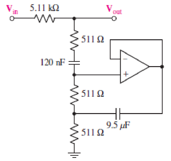
FIGURE 15.70
Expert Solution & Answer
Want to see the full answer?
Check out a sample textbook solution
Students have asked these similar questions
Discussions:
1) For the following filter,
0.15pF
Vout
Vin
3300
2) Explain what a band-pass filter is, and how it differs from
either a low-pass or a high-pass filter circuit. Also, explain what
a band-stop filter is, and draw Bode plots representative of
both band-pass and band-stop filter types.
1. A tuned circuit has a resonant frequency of 18 MHz and a bandwidth of 120 kHz. What are the upper and lower cutoff frequencies?2. What value of Q is needed to achieve a bandwidth of 4 kHz at 3.6 MHz?3. A filter has a 6-dB bandwidth of 3500 Hz and a 60-dB bandwidth of 8400 Hz. What is the shape factor?
Figure 2 (High Pass Filter)
Figure 3 (Band-Pass Filter)
Please, Find the transfer functions of these two circuits and find their cutoff frequencies. calculate.
Chapter 15 Solutions
Loose Leaf for Engineering Circuit Analysis Format: Loose-leaf
Ch. 15.1 - Write an expression for the transfer function of...Ch. 15.2 - Calculate HdB at = 146 rad/s if H(s) equals (a)...Ch. 15.2 - Prob. 3PCh. 15.2 - Draw the Bode phase plot for the transfer function...Ch. 15.2 - Construct a Bode magnitude plot for H(s) equal to...Ch. 15.2 - Draw the Bode phase plot for H(s) equal to (a)...Ch. 15.2 - Prob. 7PCh. 15.3 - A parallel resonant circuit is composed of the...Ch. 15.3 - Prob. 9PCh. 15.4 - A marginally high-Q parallel resonant circuit has...
Ch. 15.5 - A series resonant circuit has a bandwidth of 100...Ch. 15.6 - Referring to the circuit of Fig. 15.25a, let R1 =...Ch. 15.6 - Prob. 13PCh. 15.6 - Prob. 14PCh. 15.6 - The series combination of 10 and 10 nF is in...Ch. 15.7 - A parallel resonant circuit is defined by C = 0.01...Ch. 15.8 - Design a high-pass filter with a cutoff frequency...Ch. 15.8 - Design a bandpass filter with a low-frequency...Ch. 15.8 - Design a low-pass filter circuit with a gain of 30...Ch. 15 - For the RL circuit in Fig. 15.52, (a) determine...Ch. 15 - For the RL circuit in Fig. 15.52, switch the...Ch. 15 - Examine the series RLC circuit in Fig. 15.53, with...Ch. 15 - For the circuit in Fig. 15.54, (a) derive an...Ch. 15 - For the circuit in Fig. 15.55, (a) derive an...Ch. 15 - For the circuit in Fig. 15.56, (a) determine the...Ch. 15 - For the circuit in Fig. 15.57, (a) determine the...Ch. 15 - Sketch the Bode magnitude and phase plots for the...Ch. 15 - Use the Bode approach to sketch the magnitude of...Ch. 15 - If a particular network is described by transfer...Ch. 15 - Use MATLAB to plot the magnitude and phase Bode...Ch. 15 - Determine the Bode magnitude plot for the...Ch. 15 - Determine the Bode magnitude and phase plot for...Ch. 15 - Prob. 15ECh. 15 - Prob. 16ECh. 15 - For the circuit of Fig. 15.56, construct a...Ch. 15 - Construct a magnitude and phase Bode plot for the...Ch. 15 - For the circuit in Fig. 15.54, use LTspice to...Ch. 15 - For the circuit in Fig. 15.55, use LTspice to...Ch. 15 - Prob. 21ECh. 15 - A certain parallel RLC circuit is built using...Ch. 15 - A parallel RLC network is constructed using R = 5...Ch. 15 - Prob. 24ECh. 15 - Delete the 2 resistor in the network of Fig....Ch. 15 - Delete the 1 resistor in the network of Fig....Ch. 15 - Prob. 28ECh. 15 - Prob. 29ECh. 15 - Prob. 30ECh. 15 - A parallel RLC network is constructed with a 200 H...Ch. 15 - Prob. 32ECh. 15 - A parallel RLC circuit is constructed such that it...Ch. 15 - Prob. 34ECh. 15 - Prob. 35ECh. 15 - An RLC circuit is constructed using R = 5 , L = 20...Ch. 15 - Prob. 37ECh. 15 - Prob. 38ECh. 15 - For the network of Fig. 15.25a, R1 = 100 , R2 =...Ch. 15 - Assuming an operating frequency of 200 rad/s, find...Ch. 15 - Prob. 41ECh. 15 - Prob. 42ECh. 15 - For the circuit shown in Fig. 15.64, the voltage...Ch. 15 - Prob. 44ECh. 15 - Prob. 45ECh. 15 - Prob. 46ECh. 15 - The filter shown in Fig. 15.66a has the response...Ch. 15 - Prob. 48ECh. 15 - Examine the filter for the circuit in Fig. 15.68....Ch. 15 - Examine the filter for the circuit in Fig. 15.69....Ch. 15 - (a)Design a high-pass filter with a corner...Ch. 15 - (a) Design a low-pass filter with a break...Ch. 15 - Prob. 53ECh. 15 - Prob. 54ECh. 15 - Design a low-pass filter characterized by a...Ch. 15 - Prob. 56ECh. 15 - The circuit in Fig. 15.70 is known as a notch...Ch. 15 - (a) Design a two-stage op amp filter circuit with...Ch. 15 - Design a circuit which removes the entire audio...Ch. 15 - Prob. 61ECh. 15 - If a high-pass filter is required having gain of 6...Ch. 15 - (a) Design a second-order high-pass Butterworth...Ch. 15 - Design a fourth-order high-pass Butterworth filter...Ch. 15 - (a) Design a Sallen-Key low-pass filter with a...Ch. 15 - (a) Design a Sallen-Key low-pass filter with a...Ch. 15 - A piezoelectric sensor has an equivalent circuit...Ch. 15 - Design a parallel resonant circuit for an AM radio...Ch. 15 - The network of Fig. 15.72 was implemented as a...Ch. 15 - Determine the effect of component tolerance on the...
Additional Engineering Textbook Solutions
Find more solutions based on key concepts
The current source in the circuit shown generates the current pulse
Find (a) v (0); (b) the instant of time gr...
Electric Circuits. (11th Edition)
For the “tank” circuit in Fig. 14.79, find the resonant frequency.
Figure 14.79
For Probs. 14.39, 14.71, and 1...
Fundamentals of Electric Circuits
Write the nodal equations for the network of Fig. 8.137 using the general approach. Find the nodal voltages usi...
Introductory Circuit Analysis (13th Edition)
Design an ideal inverting op-amp circuit such that the voltage gain is Av=25 . The maximum current in any resis...
Microelectronics: Circuit Analysis and Design
Analog Voltmeter Design Figure P2-98(a) shows a voltmeter circuit consisting of a D'Arsonval meter, two series ...
ANALYSIS+DESIGN OF LINEAR CIRCUITS(LL)
How many coulombs do 93.8 1016 electrons represent?
Principles Of Electric Circuits
Knowledge Booster


Learn more about
Need a deep-dive on the concept behind this application? Look no further. Learn more about this topic, electrical-engineering and related others by exploring similar questions and additional content below.Similar questions
- Design an active highpass filter with a gain of 10, a corner frequency of 2 kHz, and a gain roll-off rate of 40 dB/decade.arrow_forward. Design a low-pass active filter of cut-off frequency 100 kHz and gain 32 dB.(assume C = 0.1nF)arrow_forwardDesign an active lowpass filter with dc gain of 0.5 and corner frequency of 250Hz. Then draw the circuit diagram for this filter.arrow_forward
- I want the answer in detail and as quickly as possible please Q/ Using capacitors and resistors, design A - (band-pass filters) with Fl=108HZ and Fh=112HZ. B - Design (band-pass filters) with Fl = 218HZ and Fh = 223HZ. %3D ((And make sure that the values are available in the market))arrow_forwardDesign a Passive RL based Band Pass filter for specific bandwidth. A filter which allows the signals which have frequencies in the range of 80 Hz to 800 Hz.arrow_forwardDesign a single pole low pass filter with a gain of 10 in the passband and a 3dB frequency of 5kHz. What is the value of R1?arrow_forward
- 3. In the circuit below, assume the op amp is ideal. a. Find the transfer function Vo/Vin (leave Rf, Rs and C as variables). b. What type of filter is it? If Rf = 10kn, Rs = 1k0, C=2µF: c. Find the passband gain. d. Find the corner frequency. e. Sketch the Bode plot for the magnitude of the transfer function. Vin C R Voarrow_forwardBuild a 4th order high-pass filter with a corner frequency of 50 kHz and a transition that is as steep as possible. Other parameters can be freely selected.arrow_forwardProblem 4: Consider the electrical circuit depicted in the figure below. Vin L Vout 1. Compute the transfer function G(jw) = Dout(jw) Vin (jw) 2. Draw its Bode magnitude plot and based on the shape of the plot explain the characteristic of the circuit above. What is the name of this circuit? 3. Assuming that L= 30 mH, compute the value of the resistor R such that cutoff frequency of the circuit above is 200 kHz.arrow_forward
- (c) Design a series RLC bandpass filter with cutoff frequencies fc₁ = 1 KHz, fcz = 20 KHz, using a 100 resistor. Draw the circuit and label all the components, including circuit values, including input and output. Also draw the magnitude and phase plots for the filter. Amplitude [dB] 50 40 30- Phase [°] 10 of- -10... -20... -30- -40- -50 0.1 180 135 90 C 45 of -45- -90 -135- -180 0.1 1 1 10 10 100 100 1000 1000 10,000 Freq. (Hz) 10,000 Freq. (Hz)arrow_forwardGive the other types of low-pass filters. Draw the circuit and frequency response of each.arrow_forwardHw. #I R3 RI using the followiag Rz Vi circuit. RL O ) Derive the transfer function Tis) = Vols) V:(s) b) what is the order of then filter? c) what type of filter is thisarrow_forward
arrow_back_ios
SEE MORE QUESTIONS
arrow_forward_ios
Recommended textbooks for you
 Introductory Circuit Analysis (13th Edition)Electrical EngineeringISBN:9780133923605Author:Robert L. BoylestadPublisher:PEARSON
 Delmar's Standard Textbook Of ElectricityElectrical EngineeringISBN:9781337900348Author:Stephen L. HermanPublisher:Cengage Learning
 Programmable Logic ControllersElectrical EngineeringISBN:9780073373843Author:Frank D. PetruzellaPublisher:McGraw-Hill Education
 Fundamentals of Electric CircuitsElectrical EngineeringISBN:9780078028229Author:Charles K Alexander, Matthew SadikuPublisher:McGraw-Hill Education
 Electric Circuits. (11th Edition)Electrical EngineeringISBN:9780134746968Author:James W. Nilsson, Susan RiedelPublisher:PEARSON
 Engineering ElectromagneticsElectrical EngineeringISBN:9780078028151Author:Hayt, William H. (william Hart), Jr, BUCK, John A.Publisher:Mcgraw-hill Education,
Introductory Circuit Analysis (13th Edition)
Electrical Engineering
ISBN:9780133923605
Author:Robert L. Boylestad
Publisher:PEARSON
Delmar's Standard Textbook Of Electricity
Electrical Engineering
ISBN:9781337900348
Author:Stephen L. Herman
Publisher:Cengage Learning
Programmable Logic Controllers
Electrical Engineering
ISBN:9780073373843
Author:Frank D. Petruzella
Publisher:McGraw-Hill Education
Fundamentals of Electric Circuits
Electrical Engineering
ISBN:9780078028229
Author:Charles K Alexander, Matthew Sadiku
Publisher:McGraw-Hill Education
Electric Circuits. (11th Edition)
Electrical Engineering
ISBN:9780134746968
Author:James W. Nilsson, Susan Riedel
Publisher:PEARSON
Engineering Electromagnetics
Electrical Engineering
ISBN:9780078028151
Author:Hayt, William H. (william Hart), Jr, BUCK, John A.
Publisher:Mcgraw-hill Education,
What is Filter & Classification of Filters | Four Types of Filters | Electronic Devices & Circuits; Author: SimplyInfo;https://www.youtube.com/watch?v=9x1Sjz-VPSg;License: Standard Youtube License