
Applied Statics and Strength of Materials (6th Edition)
6th Edition
ISBN: 9780133840544
Author: George F. Limbrunner, Craig D'Allaird, Leonard Spiegel
Publisher: PEARSON
expand_more
expand_more
format_list_bulleted
Concept explainers
Videos
Textbook Question
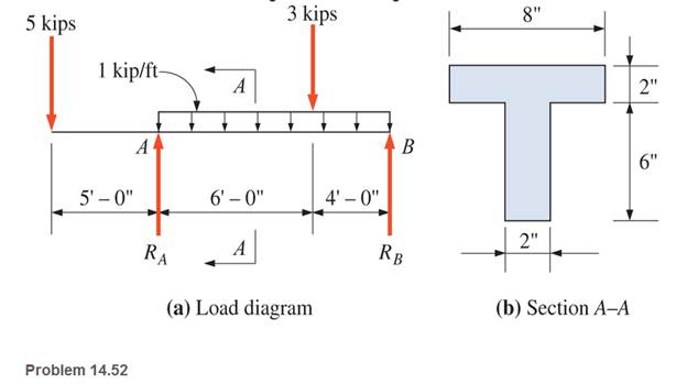
Chapter 14, Problem 14.52SP
For the beam shown, calculate the maximum tensile and compressive bending stresses and the maximum shear stresses. Neglect the beam weight.
Expert Solution & Answer

Trending nowThis is a popular solution!

Learn your wayIncludes step-by-step video

schedule15:02
Students have asked these similar questions
Figure 2 shows a built-up cross-section of a horizontal beam which has a maximum shear force of 100 KN. Calculate the shear stresses and plot the shear stress distribution (Approximate the shear stress at the Neutral axis).
Analyze the beam for stresses at point A and B due to combined effect of loading. Force F is equal to 5000 lbs and P is equal to 3500 lbs.
For the given fig find the correct representation of the longitudinal variation of the bending stress
Chapter 14 Solutions
Applied Statics and Strength of Materials (6th Edition)
Ch. 14 - Calculate the section modulus for: (a) a 6 -in-by-...Ch. 14 - Calculate the section modulus (with respect to the...Ch. 14 - Prob. 14.3PCh. 14 - Rework Problem 14.3 changing the orientation of...Ch. 14 - Assume that the timber member (a) of Problem 14.2...Ch. 14 - The structural steel built-up member (b) of...Ch. 14 - A round steel rod, 25 mm in diameter, is subjected...Ch. 14 - A square steel bar, 38 mm on each side, is used as...Ch. 14 - Calculate the moment strength for a W36302...Ch. 14 - Calculate the allowable bending moment for a solid...
Ch. 14 - The beams of cross sections shown are subjected to...Ch. 14 - A solid rectangular simply supported timber beam 6...Ch. 14 - A W1430 supports the loads shown. Calculate the...Ch. 14 - If the allowable shear stress is 100 MPa,...Ch. 14 - A steel pin 112 in diameter is subjected to a...Ch. 14 - A timber power-line pole is 10 in. in diameter at...Ch. 14 - Calculate the value of S and Z and the shape...Ch. 14 - For beams that have cross sections as shown for...Ch. 14 - Calculate the maximum load P that the beam shown...Ch. 14 - A 412 (S4S) hem-fir timber beam carries a...Ch. 14 - A simply supported W1636 A992 steel beam carries a...Ch. 14 - A W250115 steel wide-flange section supports a...Ch. 14 - Assume that the floor joist dimensions of Example...Ch. 14 - Calculate the allowable superimposed uniformly...Ch. 14 - A 3 -in.-by- 12 -in. (S4S) scaffold timber plank...Ch. 14 - For the following computer problems, any...Ch. 14 - For the following computer problems, any...Ch. 14 - For the following computer problems, any...Ch. 14 - Calculate the section modulus with respect to the...Ch. 14 - The timber box section (a) of Problem 14.29 is...Ch. 14 - A timber beam is subjected to a maximum bending...Ch. 14 - Rework Problem 14.31 assuming that the beam is...Ch. 14 - A 12 -in.-diameter steel rod projects 2 ft...Ch. 14 - Calculate the maximum bending stress in a W530101...Ch. 14 - A cantilever cast-iron beam is 6 ft long and has a...Ch. 14 - 14.36 Calculate the moment strength for a...Ch. 14 - A W813 steel wide-flange beam on a 20 -ft span is...Ch. 14 - A simply supported beam with a cruciform cross...Ch. 14 - A rectangular beam 100 mm in width and 250 mm in...Ch. 14 - The timber box section (a) of Problem 14.29 is...Ch. 14 - For the I-shaped timber beam shown, calculate the...Ch. 14 - 14.42 A steel wide-flange beam is oriented so that...Ch. 14 - A W1045steel wide-flange beam supports a uniformly...Ch. 14 - 14.44 A steel wide-flange section is subjected to...Ch. 14 - A W30108 steel wide-flange beam is simply...Ch. 14 - A W612 is strengthened with a 34 -in.-by- 34 -in....Ch. 14 - Four wood boards 1 in. by 6 in. in cross section...Ch. 14 - A lintel consists of two 8 -in.-by- 12 in. steel...Ch. 14 - A 50 -mm-by- 300 -mm scaffold timber plank, placed...Ch. 14 - A laminated wood beam is built up by gluing...Ch. 14 - A rectangular hollow shape carries loads as shown....Ch. 14 - For the beam shown, calculate the maximum tensile...Ch. 14 - 14.53 A box beam is built up of four -in.-by--in....Ch. 14 - 14.54 Find the value of the loads P that can be...Ch. 14 - 14.55 Solve Problem 14.54 assuming that the timber...Ch. 14 - Calculate the values of S and Z and the shape...Ch. 14 - 14.57 A is supported on simple supports on a -ft...
Additional Engineering Textbook Solutions
Find more solutions based on key concepts
What parts are included in the vehicle chassis?
Automotive Technology: Principles, Diagnosis, and Service (5th Edition)
The two identical boards are bolted together to form the beam. Determine the maximum spacing s of the bolts to ...
Statics and Mechanics of Materials (5th Edition)
What parts are included in the vehicle chassis?
Automotive Technology: Principles, Diagnosis, And Service (6th Edition) (halderman Automotive Series)
The impulses created by a falling weight onto a sample of URETHANE foam and CONFOR foam.
Engineering Mechanics: Statics & Dynamics (14th Edition)
Replace this loading by an equivalent resultant force and specify its location, measured from point O.
INTERNATIONAL EDITION---Engineering Mechanics: Statics, 14th edition (SI unit)
11. If a pump moves water at 70 gallons per minute [gal/min or gpm], what is the volumetric flow rate in units ...
Thinking Like an Engineer: An Active Learning Approach (4th Edition)
Knowledge Booster


Learn more about
Need a deep-dive on the concept behind this application? Look no further. Learn more about this topic, mechanical-engineering and related others by exploring similar questions and additional content below.Similar questions
- Derive the formula for the bending stress of a beam with a rectangular cross section and triangular cross secrion. Thank youarrow_forwardIf the shear force is 50 kN, calculate the shear load per metre length at the top of the flangeof the T-section. [Start your calculations by setting the origin on the bottom of the cross- section].arrow_forwardFor the beam shown in the figure below, deduct the expressions for V and M. Plot the Shear Effort and Bending Moment diagramsarrow_forward
- For the beam shown, find the reactions at the supports and plot the shear-force and bending-moment diagrams. Label the diagrams properly and provide values at all key points.arrow_forwardDraw diagrams of shear force and bending moment for beam and loading shown. Calculate the maximum tensile and compressive stresses in the beam. X=407 N/m Y=2.21 m Z=51,4 mmarrow_forwardFill in the blanks. Draw and label the shear and bending moment diagrams. Find the normal stress at the POI. Make sure that you label the shear and bending moment diagrams with all values shown. Write the equations forX being between 15 and 19 feetarrow_forward
- For the beam shown, find the reactions at the supports and plot the shear-force and bending-moment diagrams. Label the diagrams properly and provide values at all key points within the diagrams.arrow_forwardA circular shaft is subjected to combined loads of bending M and torque T. With the help of Mohr's circle diagram, represent the stresses on an element of the shaft surface. From this diagram or by calculation, find the maximum shear stress due to the combined effect of these gradually applied loads of M and T.arrow_forwardThe cantilever beam in Fig. (a) carries a triangular load, the intensity of which varies from zero at the left end to 360 lb/ft at the right end. In addition, a 1000-lb upward vertical load acts at the free end of the beam. (1) Derive the shear force and bending moment equations, and (2) draw the shear force and bending moment diagrams. Neglect the weight of the beamarrow_forward
- For the beam shown on the picture select the corresponding shear force and bending moment diagrams from belowarrow_forwardA cantilever beammade up of a material with the density of 2000kg/m3 has a circular cross section with a diameter of 150mm. In addition to the self weight, the beam is subjected concentrated point load of 88 kN at its midspan. Find out the flexural and shear stresses at top, bottom and neutral axis of the cross section produced due to the maximum bending moment if the span length of the beam is 4m. Consider the self weight of the beam in solving the question.arrow_forwardCalculate the normal stress, shear stress, and bending deformation of the beam. (Point A has a pinned support, while point C has a roller support)arrow_forward
arrow_back_ios
SEE MORE QUESTIONS
arrow_forward_ios
Recommended textbooks for you
 Elements Of ElectromagneticsMechanical EngineeringISBN:9780190698614Author:Sadiku, Matthew N. O.Publisher:Oxford University Press
 Mechanics of Materials (10th Edition)Mechanical EngineeringISBN:9780134319650Author:Russell C. HibbelerPublisher:PEARSON
 Thermodynamics: An Engineering ApproachMechanical EngineeringISBN:9781259822674Author:Yunus A. Cengel Dr., Michael A. BolesPublisher:McGraw-Hill Education
 Control Systems EngineeringMechanical EngineeringISBN:9781118170519Author:Norman S. NisePublisher:WILEY
 Mechanics of Materials (MindTap Course List)Mechanical EngineeringISBN:9781337093347Author:Barry J. Goodno, James M. GerePublisher:Cengage Learning
 Engineering Mechanics: StaticsMechanical EngineeringISBN:9781118807330Author:James L. Meriam, L. G. Kraige, J. N. BoltonPublisher:WILEY
Elements Of Electromagnetics
Mechanical Engineering
ISBN:9780190698614
Author:Sadiku, Matthew N. O.
Publisher:Oxford University Press
Mechanics of Materials (10th Edition)
Mechanical Engineering
ISBN:9780134319650
Author:Russell C. Hibbeler
Publisher:PEARSON
Thermodynamics: An Engineering Approach
Mechanical Engineering
ISBN:9781259822674
Author:Yunus A. Cengel Dr., Michael A. Boles
Publisher:McGraw-Hill Education
Control Systems Engineering
Mechanical Engineering
ISBN:9781118170519
Author:Norman S. Nise
Publisher:WILEY
Mechanics of Materials (MindTap Course List)
Mechanical Engineering
ISBN:9781337093347
Author:Barry J. Goodno, James M. Gere
Publisher:Cengage Learning
Engineering Mechanics: Statics
Mechanical Engineering
ISBN:9781118807330
Author:James L. Meriam, L. G. Kraige, J. N. Bolton
Publisher:WILEY
Types of Manufacturing Process | Manufacturing Processes; Author: Magic Marks;https://www.youtube.com/watch?v=koULXptaBTs;License: Standard Youtube License