
Applied Statics and Strength of Materials (6th Edition)
6th Edition
ISBN: 9780133840544
Author: George F. Limbrunner, Craig D'Allaird, Leonard Spiegel
Publisher: PEARSON
expand_more
expand_more
format_list_bulleted
Concept explainers
Videos
Textbook Question
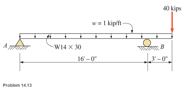
Chapter 14, Problem 14.13P
A
Expert Solution & Answer
Want to see the full answer?
Check out a sample textbook solution
Students have asked these similar questions
Solve the following questions: Plot the shear and moment diagrams for the beam loaded with both distributed and point loads. What is the value of the shear at x = 0 m?
QUESTION 3
If the allowable bending stresses for a beam in one application is 6 kip/in2 in tension. The cross-section of the beam is W8 x 40.
If the beam is 10 foot long and simply supported and has a concentrated load applied at x = 3 ft as shown below.
• Generate the shear force and bending moment diagram in terms of P;
• Based on the allowable maximum bending moment you just obtained above, calculate/ input the mazimm allowable value of the load P:
please, pay attention to units, and calculate your answer to 1 decimal place..
3 ft
7 ft
kip.
Calculate the shear force and bending moment in each beam at sections 1-1, 2-2 and 3-3.
Chapter 14 Solutions
Applied Statics and Strength of Materials (6th Edition)
Ch. 14 - Calculate the section modulus for: (a) a 6 -in-by-...Ch. 14 - Calculate the section modulus (with respect to the...Ch. 14 - Prob. 14.3PCh. 14 - Rework Problem 14.3 changing the orientation of...Ch. 14 - Assume that the timber member (a) of Problem 14.2...Ch. 14 - The structural steel built-up member (b) of...Ch. 14 - A round steel rod, 25 mm in diameter, is subjected...Ch. 14 - A square steel bar, 38 mm on each side, is used as...Ch. 14 - Calculate the moment strength for a W36302...Ch. 14 - Calculate the allowable bending moment for a solid...
Ch. 14 - The beams of cross sections shown are subjected to...Ch. 14 - A solid rectangular simply supported timber beam 6...Ch. 14 - A W1430 supports the loads shown. Calculate the...Ch. 14 - If the allowable shear stress is 100 MPa,...Ch. 14 - A steel pin 112 in diameter is subjected to a...Ch. 14 - A timber power-line pole is 10 in. in diameter at...Ch. 14 - Calculate the value of S and Z and the shape...Ch. 14 - For beams that have cross sections as shown for...Ch. 14 - Calculate the maximum load P that the beam shown...Ch. 14 - A 412 (S4S) hem-fir timber beam carries a...Ch. 14 - A simply supported W1636 A992 steel beam carries a...Ch. 14 - A W250115 steel wide-flange section supports a...Ch. 14 - Assume that the floor joist dimensions of Example...Ch. 14 - Calculate the allowable superimposed uniformly...Ch. 14 - A 3 -in.-by- 12 -in. (S4S) scaffold timber plank...Ch. 14 - For the following computer problems, any...Ch. 14 - For the following computer problems, any...Ch. 14 - For the following computer problems, any...Ch. 14 - Calculate the section modulus with respect to the...Ch. 14 - The timber box section (a) of Problem 14.29 is...Ch. 14 - A timber beam is subjected to a maximum bending...Ch. 14 - Rework Problem 14.31 assuming that the beam is...Ch. 14 - A 12 -in.-diameter steel rod projects 2 ft...Ch. 14 - Calculate the maximum bending stress in a W530101...Ch. 14 - A cantilever cast-iron beam is 6 ft long and has a...Ch. 14 - 14.36 Calculate the moment strength for a...Ch. 14 - A W813 steel wide-flange beam on a 20 -ft span is...Ch. 14 - A simply supported beam with a cruciform cross...Ch. 14 - A rectangular beam 100 mm in width and 250 mm in...Ch. 14 - The timber box section (a) of Problem 14.29 is...Ch. 14 - For the I-shaped timber beam shown, calculate the...Ch. 14 - 14.42 A steel wide-flange beam is oriented so that...Ch. 14 - A W1045steel wide-flange beam supports a uniformly...Ch. 14 - 14.44 A steel wide-flange section is subjected to...Ch. 14 - A W30108 steel wide-flange beam is simply...Ch. 14 - A W612 is strengthened with a 34 -in.-by- 34 -in....Ch. 14 - Four wood boards 1 in. by 6 in. in cross section...Ch. 14 - A lintel consists of two 8 -in.-by- 12 in. steel...Ch. 14 - A 50 -mm-by- 300 -mm scaffold timber plank, placed...Ch. 14 - A laminated wood beam is built up by gluing...Ch. 14 - A rectangular hollow shape carries loads as shown....Ch. 14 - For the beam shown, calculate the maximum tensile...Ch. 14 - 14.53 A box beam is built up of four -in.-by--in....Ch. 14 - 14.54 Find the value of the loads P that can be...Ch. 14 - 14.55 Solve Problem 14.54 assuming that the timber...Ch. 14 - Calculate the values of S and Z and the shape...Ch. 14 - 14.57 A is supported on simple supports on a -ft...
Knowledge Booster


Learn more about
Need a deep-dive on the concept behind this application? Look no further. Learn more about this topic, mechanical-engineering and related others by exploring similar questions and additional content below.Similar questions
- AWT305 x 41 standard steel shape is used to support the loads shown on the beam. The dimensions from the top and bottom of the shape to the centroidal axis are shown in the sketch of the cross section. Assume LAB = 3 m, LBC= 6 m, LCD= 4 m, PA = 10 kN, WBC = 7 kN/m. Consider the entire 13-m length of the beam and determine: (a) the maximum tension bending stress or at any location along the beam, and (b) the maximum compression bending stress oc at any location along the beam. A PA LAB B WBC LBC T WT305 x 41 LCD ↑ 88.9 mm. 211.1 mm D Xarrow_forwardIf the shear force is 50 kN, calculate the shear load per metre length at the top of the flangeof the T-section. [Start your calculations by setting the origin on the bottom of the cross- section].arrow_forwardAWT305 x 41 standard steel shape is used to support the loads shown on the beam. The dimensions from the top and bottom of the shape to the centroidal axis are shown in the sketch of the cross section. Assume LAB = 3 m, LBc = 7 m, LCD = 2 m, PA = 17 kN, WBC = 10 kN/m. Consider the entire 12-m length of the beam and determine: (a) the maximum tension bending stress or at any location along the beam, and (b) the maximum compression bending stress oc at any location along the beam. PA LAB Answers: (a) σT = (b) oc = i i B WBC LBC LCD Ť WT305 x 41 88.9 mm 211.1 mm MPa. MPa. Darrow_forward
- AWT305 x 41 standard steel shape is used to support the loads shown on the beam. The dimensions from the top and bottom of the shape to the centroidal axis are shown in the sketch of the cross section. Assume LAB = 2 m, LBC= 5 m, LcD = 1 m, PA = 12 kN, WBC = 12 kN/m. Consider the entire 8-m length of the beam and determine: (a) the maximum tension bending stress or at any location along the beam, and (b) the maximum compression bending stress oc at any location along the beam. A PA LAB Answers: (a) OT = (b) oc = B i 62.19 i 25.81 WBC LBC 1 WT305 x 41 C LCD 88.9 mm 211.1 mm MPa. MPa. D xarrow_forwardSolve the problem below. Provide a clean solution. Label each points from A to E then draw the load, shear and moment diagram for each given beam. Indicate each important end points.arrow_forward10c The 9.75 m long beam is simply supported at A and B shown below with a uniformly distributed load (UDL) between A and C of 4.75 kN/m and a concentrated point load of 12.50 kN at point D (i.e., midpoint between C & B). Determine the shear force in kilonewtons (kN) at the midpoint of AB (i.e., mid-beam). Assume the beam is weightless and give your answer in kilonewtons (kN) to 2 decimal places. 12.50 kN 4.75 kN/m 1.125 m A 7.50 m 2.25 m в Answer:arrow_forward
- AWT305 x 41 standard steel shape is used to support the loads shown on the beam. The dimensions from the top and bottom of the shape to the centroidal axis are shown in the sketch of the cross section. Assume LAB = 3 m, LBc = 7 m, LcD = 1 m, PA = 9 kN, WBC = 11 kN/m. Consider the entire 11-m length of the beam and determine: (a) the maximum tension bending stress or at any location along the beam, and (b) the maximum compression bending stress oc at any location along the beam. A PA LAB B WBC LBC C Z + WT305 x 41 LCD 88.9 mm 211.1 mm Xarrow_forward2. The W360 x 262 section carries a vertical shear force of 650 kN. For this section, calculate:(a) the minimum shear stress in the web;(b) the maximum shear stress in the web and(c) the percentage of the vertical shear force carried by the web.arrow_forwardCalculate the normal stress, shear stress, and bending deformation of the beam. (Point A has a pinned support, while point C has a roller support)arrow_forward
- Select the lightest-weight wide-flange beam from Appendix B that will safely support the loading. The allowable bending stress is sallow = 22 ksi and the allowable shear stress is tallow = 12 ksi.arrow_forwardN 0.3m 4.25 KN 5 KN 0.4m 100 KN 100 KN 3.0 kN m 0.1m 2 kN 200 KN 2001 This is a stainless steel beam with a circular cross section and a diameter of 7 centemeters. Calculate the reations at the fixed support and draw the bending moment, axial load, torque, shear force diagrams each with equaitions work shown.arrow_forwardDraw the shear-force and bending-moment diagram for the beam shown. Assume the upward reaction provided by the ground to be uniformly distributed. Let a = 5.0 ft, b = 3.4 ft, P = 25 kips, and w = 1.1 kips/ft. Label all significant points on each diagram. Determine the maximum value of (a) the internal shear force and (b) the internal bending moment.Note that answers may be positive or negative. Here, "maximum" refers to the largest magnitude value, but you should enter your shear force and bending moment with the correct sign, using the sign convention presented in Section 7.2 of the textbook. If the magnitudes of the largest positive and largest negative values are the same, enter a positive number.arrow_forward
arrow_back_ios
SEE MORE QUESTIONS
arrow_forward_ios
Recommended textbooks for you
 Elements Of ElectromagneticsMechanical EngineeringISBN:9780190698614Author:Sadiku, Matthew N. O.Publisher:Oxford University Press
 Mechanics of Materials (10th Edition)Mechanical EngineeringISBN:9780134319650Author:Russell C. HibbelerPublisher:PEARSON
 Thermodynamics: An Engineering ApproachMechanical EngineeringISBN:9781259822674Author:Yunus A. Cengel Dr., Michael A. BolesPublisher:McGraw-Hill Education
 Control Systems EngineeringMechanical EngineeringISBN:9781118170519Author:Norman S. NisePublisher:WILEY
 Mechanics of Materials (MindTap Course List)Mechanical EngineeringISBN:9781337093347Author:Barry J. Goodno, James M. GerePublisher:Cengage Learning
 Engineering Mechanics: StaticsMechanical EngineeringISBN:9781118807330Author:James L. Meriam, L. G. Kraige, J. N. BoltonPublisher:WILEY
Elements Of Electromagnetics
Mechanical Engineering
ISBN:9780190698614
Author:Sadiku, Matthew N. O.
Publisher:Oxford University Press
Mechanics of Materials (10th Edition)
Mechanical Engineering
ISBN:9780134319650
Author:Russell C. Hibbeler
Publisher:PEARSON
Thermodynamics: An Engineering Approach
Mechanical Engineering
ISBN:9781259822674
Author:Yunus A. Cengel Dr., Michael A. Boles
Publisher:McGraw-Hill Education
Control Systems Engineering
Mechanical Engineering
ISBN:9781118170519
Author:Norman S. Nise
Publisher:WILEY
Mechanics of Materials (MindTap Course List)
Mechanical Engineering
ISBN:9781337093347
Author:Barry J. Goodno, James M. Gere
Publisher:Cengage Learning
Engineering Mechanics: Statics
Mechanical Engineering
ISBN:9781118807330
Author:James L. Meriam, L. G. Kraige, J. N. Bolton
Publisher:WILEY
Understanding Shear Force and Bending Moment Diagrams; Author: The Efficient Engineer;https://www.youtube.com/watch?v=C-FEVzI8oe8;License: Standard YouTube License, CC-BY
Bending Stress; Author: moodlemech;https://www.youtube.com/watch?v=9QIqewkE6xM;License: Standard Youtube License