
Applied Statics and Strength of Materials (6th Edition)
6th Edition
ISBN: 9780133840544
Author: George F. Limbrunner, Craig D'Allaird, Leonard Spiegel
Publisher: PEARSON
expand_more
expand_more
format_list_bulleted
Concept explainers
Videos
Textbook Question
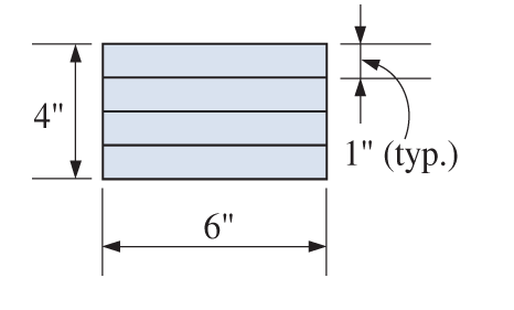
Chapter 14, Problem 14.47SP
Four wood boards
Problem 14.47 (a) the maximum bending stress (boards not glued together)
(b) the maximum bending stress if the boards are glued together
(c) the maximum shear stress in the middle glued joint
Expert Solution & Answer
Want to see the full answer?
Check out a sample textbook solution
Students have asked these similar questions
Typically, an aircraft wing is supported by a single structural spar attached to the main fuselage at the wing root as
shown. This arrangement can be idealized as a cantilever beam with a loading distribution characterizing wing pressure.
In general, holes are introduced to the structural members to reduce the overall weight of the wing (observe the rib
sections shown in B). For the idealized beam arrangement (shown in the C), assume that the cross section of the spar is
uniform and has a rectangular cross section (2" x 16"). The material is 2016-T6 Aluminum.
If four 7" diameter holes are introduced to the beam (as shown in C, below), what is the maximum increase in normal
stress? Ignore the effect of transverse shear.
(A)
(C)
Wing Root
(Assumed Fixed)
80 lb/in
1.8'
1.8'
(B)
1.8'
9'
Wing Root
+
1.8'
W
Wing Tip
Fuel Tank
Wing Tip
(Assumed Free)
QUESTION 3
If the allowable bending stresses for a beam in one application is 6 kip/in2 in tension. The cross-section of the beam is W8 x 40.
If the beam is 10 foot long and simply supported and has a concentrated load applied at x = 3 ft as shown below.
• Generate the shear force and bending moment diagram in terms of P;
• Based on the allowable maximum bending moment you just obtained above, calculate/ input the mazimm allowable value of the load P:
please, pay attention to units, and calculate your answer to 1 decimal place..
3 ft
7 ft
kip.
A beam simply supported at the ends of a 25-ft span carries a uniformly distributed load of 1000 lb/ft over its entire length. The
lightest S section available is S12 x 50 with a section modulus of 50.8 in3. If the allowable stress is 20 ksi, fınd the actual bending
moment.
82, 146.78 ft Ibs.
O 81,476.56 ft Ibs.
82,031.25 ft.lbs.
O None of these
Chapter 14 Solutions
Applied Statics and Strength of Materials (6th Edition)
Ch. 14 - Calculate the section modulus for: (a) a 6 -in-by-...Ch. 14 - Calculate the section modulus (with respect to the...Ch. 14 - Prob. 14.3PCh. 14 - Rework Problem 14.3 changing the orientation of...Ch. 14 - Assume that the timber member (a) of Problem 14.2...Ch. 14 - The structural steel built-up member (b) of...Ch. 14 - A round steel rod, 25 mm in diameter, is subjected...Ch. 14 - A square steel bar, 38 mm on each side, is used as...Ch. 14 - Calculate the moment strength for a W36302...Ch. 14 - Calculate the allowable bending moment for a solid...
Ch. 14 - The beams of cross sections shown are subjected to...Ch. 14 - A solid rectangular simply supported timber beam 6...Ch. 14 - A W1430 supports the loads shown. Calculate the...Ch. 14 - If the allowable shear stress is 100 MPa,...Ch. 14 - A steel pin 112 in diameter is subjected to a...Ch. 14 - A timber power-line pole is 10 in. in diameter at...Ch. 14 - Calculate the value of S and Z and the shape...Ch. 14 - For beams that have cross sections as shown for...Ch. 14 - Calculate the maximum load P that the beam shown...Ch. 14 - A 412 (S4S) hem-fir timber beam carries a...Ch. 14 - A simply supported W1636 A992 steel beam carries a...Ch. 14 - A W250115 steel wide-flange section supports a...Ch. 14 - Assume that the floor joist dimensions of Example...Ch. 14 - Calculate the allowable superimposed uniformly...Ch. 14 - A 3 -in.-by- 12 -in. (S4S) scaffold timber plank...Ch. 14 - For the following computer problems, any...Ch. 14 - For the following computer problems, any...Ch. 14 - For the following computer problems, any...Ch. 14 - Calculate the section modulus with respect to the...Ch. 14 - The timber box section (a) of Problem 14.29 is...Ch. 14 - A timber beam is subjected to a maximum bending...Ch. 14 - Rework Problem 14.31 assuming that the beam is...Ch. 14 - A 12 -in.-diameter steel rod projects 2 ft...Ch. 14 - Calculate the maximum bending stress in a W530101...Ch. 14 - A cantilever cast-iron beam is 6 ft long and has a...Ch. 14 - 14.36 Calculate the moment strength for a...Ch. 14 - A W813 steel wide-flange beam on a 20 -ft span is...Ch. 14 - A simply supported beam with a cruciform cross...Ch. 14 - A rectangular beam 100 mm in width and 250 mm in...Ch. 14 - The timber box section (a) of Problem 14.29 is...Ch. 14 - For the I-shaped timber beam shown, calculate the...Ch. 14 - 14.42 A steel wide-flange beam is oriented so that...Ch. 14 - A W1045steel wide-flange beam supports a uniformly...Ch. 14 - 14.44 A steel wide-flange section is subjected to...Ch. 14 - A W30108 steel wide-flange beam is simply...Ch. 14 - A W612 is strengthened with a 34 -in.-by- 34 -in....Ch. 14 - Four wood boards 1 in. by 6 in. in cross section...Ch. 14 - A lintel consists of two 8 -in.-by- 12 in. steel...Ch. 14 - A 50 -mm-by- 300 -mm scaffold timber plank, placed...Ch. 14 - A laminated wood beam is built up by gluing...Ch. 14 - A rectangular hollow shape carries loads as shown....Ch. 14 - For the beam shown, calculate the maximum tensile...Ch. 14 - 14.53 A box beam is built up of four -in.-by--in....Ch. 14 - 14.54 Find the value of the loads P that can be...Ch. 14 - 14.55 Solve Problem 14.54 assuming that the timber...Ch. 14 - Calculate the values of S and Z and the shape...Ch. 14 - 14.57 A is supported on simple supports on a -ft...
Knowledge Booster


Learn more about
Need a deep-dive on the concept behind this application? Look no further. Learn more about this topic, mechanical-engineering and related others by exploring similar questions and additional content below.Similar questions
- Calculate the modulus of section of rectangle beam of breadth 120 mm and height 200 mm.arrow_forwardA simply supported beam, 50mm wide by 100mm high and 300 mm long is subjected to a concentrated load of 3000 N at a point 100 mm from one of the supports. Draw the shear force and bending moment diagrams for the beam.arrow_forward1. A bending moment of 5800 lb-in. is applied to a beam having a rectangular cross- section with dimensions of 0.75 in. × 1.50 in. Compute the maximum bending stress in the beam (a) if the vertical side is 1.50 in. and (b) if the vertical side is 0.75 in. 1arrow_forward
- Derive the formula for the bending stress of a beam with a rectangular cross section and triangular cross secrion. Thank youarrow_forwardAn overhanging beam is loaded as indicated. In order to accommodate communication cables to be installed later the beam is manufactured with two circular channels running through its length. The beam has a weight of q = 300 N/m. Calculate (a) the value and position of the maximum bending moment and sketch the relevant bending moment and shear force diagrams, (b) the position of the neutral axis, and (c) the maximum compressive and tension stress in the beam due to the bending. 2m 3 KN 3m B Bm 1 KN 100 mm 100 mm 20 mm H 30 mmarrow_forwardThe beam shown will be constructed from a standard steel W-shape using an allowable bending stress of 40.4 ksi. Assume P = 51 kips, L1=6.6 ft, and L2=19.8 ft. (a) Determine the minimum section modulus required for this beam. (b) From the table below, select the lightest W shape that can be used for this beam. (c) What is the total weight of the steel beam itself (i.e., not including the loads that are carried by the beam)?arrow_forward
- A simply supported beam of hollow rectangular cross section is 100mm deep and 60mm wide with a wall thickness of 10mm. The beam has a span of 6m and carries a load as shown . Neglecting the weight of the beam draw a bending moment diagram and calculate the maximum bending moment. And determine the maximum bending stress in the material.arrow_forwardThe shape of the bending moment diagram for a uniform cantilever beam a. carrying a uniformly distributed load over its length isarrow_forwardFor the T-beam formed by welded structural steel plates, assume that it has: linearly elastic behavior, simple bending, and the self-weight is negligible. determine a. The maximum bending stress in ton/cm2 b. Maximum average shear stress in ton/cm2 c. Deflection in cm under load, apply overlaparrow_forward
- From the given beam shown below, compute the following: 20 mm 80 mm 160 mm NA 1.0 m 1.0m H– 20 mm 1. Distance between top of the beam to Neutral Axis or "c top". 2. Moment of Inertia at Neutral Axis or "I" 3. What is the maximum safe value of P if the working stress in shear is 6 MPa? 4. Using the maximum safe value of P what is the Maximum shear? 5. Using the maximum safe value of P what is the Maximum Moment?arrow_forwardSelect the lightest-weight wide-flange beam with the shortest depth from Appendix B that will safely support the loading shown. The allowable bending stress is sallow = 24 ksi and the allowable shear stress of tallow = 14 ksi.arrow_forwardProblem #5: For the 2D beam below, with F 15 kips, M, = 7 kip-ft, and shear and bending moment diagrams. Report your answer in kip and kip-ft to one decimal place. w,= 2.5 kip/ft draw the Wo F, Fo Mo Mo 2.0 ft 1.0 ft 5.0 ft 2.0 ftarrow_forward
arrow_back_ios
SEE MORE QUESTIONS
arrow_forward_ios
Recommended textbooks for you
 Elements Of ElectromagneticsMechanical EngineeringISBN:9780190698614Author:Sadiku, Matthew N. O.Publisher:Oxford University Press
 Mechanics of Materials (10th Edition)Mechanical EngineeringISBN:9780134319650Author:Russell C. HibbelerPublisher:PEARSON
 Thermodynamics: An Engineering ApproachMechanical EngineeringISBN:9781259822674Author:Yunus A. Cengel Dr., Michael A. BolesPublisher:McGraw-Hill Education
 Control Systems EngineeringMechanical EngineeringISBN:9781118170519Author:Norman S. NisePublisher:WILEY
 Mechanics of Materials (MindTap Course List)Mechanical EngineeringISBN:9781337093347Author:Barry J. Goodno, James M. GerePublisher:Cengage Learning
 Engineering Mechanics: StaticsMechanical EngineeringISBN:9781118807330Author:James L. Meriam, L. G. Kraige, J. N. BoltonPublisher:WILEY
Elements Of Electromagnetics
Mechanical Engineering
ISBN:9780190698614
Author:Sadiku, Matthew N. O.
Publisher:Oxford University Press
Mechanics of Materials (10th Edition)
Mechanical Engineering
ISBN:9780134319650
Author:Russell C. Hibbeler
Publisher:PEARSON
Thermodynamics: An Engineering Approach
Mechanical Engineering
ISBN:9781259822674
Author:Yunus A. Cengel Dr., Michael A. Boles
Publisher:McGraw-Hill Education
Control Systems Engineering
Mechanical Engineering
ISBN:9781118170519
Author:Norman S. Nise
Publisher:WILEY
Mechanics of Materials (MindTap Course List)
Mechanical Engineering
ISBN:9781337093347
Author:Barry J. Goodno, James M. Gere
Publisher:Cengage Learning
Engineering Mechanics: Statics
Mechanical Engineering
ISBN:9781118807330
Author:James L. Meriam, L. G. Kraige, J. N. Bolton
Publisher:WILEY
Types of Manufacturing Process | Manufacturing Processes; Author: Magic Marks;https://www.youtube.com/watch?v=koULXptaBTs;License: Standard Youtube License