
Applied Statics and Strength of Materials (6th Edition)
6th Edition
ISBN: 9780133840544
Author: George F. Limbrunner, Craig D'Allaird, Leonard Spiegel
Publisher: PEARSON
expand_more
expand_more
format_list_bulleted
Videos
Textbook Question
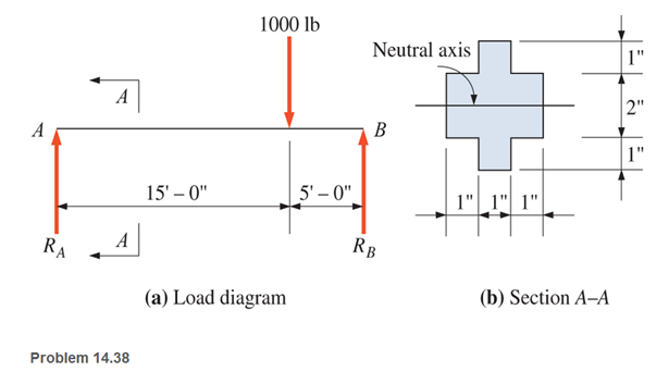
Chapter 14, Problem 14.38SP
A simply supported beam with a cruciform cross section is loaded as shown. Calculate the maximum horizontal shear stress. Neglect the weight of the beam, (Hint: Check two planes in the cross section.)
Expert Solution & Answer
Want to see the full answer?
Check out a sample textbook solution
Students have asked these similar questions
Calculate the normal stress, shear stress, and bending deformation of the beam. (Point A has a pinned support, while point C has a roller support)
A simply supported 3 m long beam with a point load
of 5 kN and a cross section of 50 mm * 80 mm is
applied in the middle of the beam. Calculate the
maximum transverse shear stress acting on the
beam cross section.
Derive the formula for the bending stress of a beam with a rectangular cross section and triangular cross secrion.
Thank you
Chapter 14 Solutions
Applied Statics and Strength of Materials (6th Edition)
Ch. 14 - Calculate the section modulus for: (a) a 6 -in-by-...Ch. 14 - Calculate the section modulus (with respect to the...Ch. 14 - Prob. 14.3PCh. 14 - Rework Problem 14.3 changing the orientation of...Ch. 14 - Assume that the timber member (a) of Problem 14.2...Ch. 14 - The structural steel built-up member (b) of...Ch. 14 - A round steel rod, 25 mm in diameter, is subjected...Ch. 14 - A square steel bar, 38 mm on each side, is used as...Ch. 14 - Calculate the moment strength for a W36302...Ch. 14 - Calculate the allowable bending moment for a solid...
Ch. 14 - The beams of cross sections shown are subjected to...Ch. 14 - A solid rectangular simply supported timber beam 6...Ch. 14 - A W1430 supports the loads shown. Calculate the...Ch. 14 - If the allowable shear stress is 100 MPa,...Ch. 14 - A steel pin 112 in diameter is subjected to a...Ch. 14 - A timber power-line pole is 10 in. in diameter at...Ch. 14 - Calculate the value of S and Z and the shape...Ch. 14 - For beams that have cross sections as shown for...Ch. 14 - Calculate the maximum load P that the beam shown...Ch. 14 - A 412 (S4S) hem-fir timber beam carries a...Ch. 14 - A simply supported W1636 A992 steel beam carries a...Ch. 14 - A W250115 steel wide-flange section supports a...Ch. 14 - Assume that the floor joist dimensions of Example...Ch. 14 - Calculate the allowable superimposed uniformly...Ch. 14 - A 3 -in.-by- 12 -in. (S4S) scaffold timber plank...Ch. 14 - For the following computer problems, any...Ch. 14 - For the following computer problems, any...Ch. 14 - For the following computer problems, any...Ch. 14 - Calculate the section modulus with respect to the...Ch. 14 - The timber box section (a) of Problem 14.29 is...Ch. 14 - A timber beam is subjected to a maximum bending...Ch. 14 - Rework Problem 14.31 assuming that the beam is...Ch. 14 - A 12 -in.-diameter steel rod projects 2 ft...Ch. 14 - Calculate the maximum bending stress in a W530101...Ch. 14 - A cantilever cast-iron beam is 6 ft long and has a...Ch. 14 - 14.36 Calculate the moment strength for a...Ch. 14 - A W813 steel wide-flange beam on a 20 -ft span is...Ch. 14 - A simply supported beam with a cruciform cross...Ch. 14 - A rectangular beam 100 mm in width and 250 mm in...Ch. 14 - The timber box section (a) of Problem 14.29 is...Ch. 14 - For the I-shaped timber beam shown, calculate the...Ch. 14 - 14.42 A steel wide-flange beam is oriented so that...Ch. 14 - A W1045steel wide-flange beam supports a uniformly...Ch. 14 - 14.44 A steel wide-flange section is subjected to...Ch. 14 - A W30108 steel wide-flange beam is simply...Ch. 14 - A W612 is strengthened with a 34 -in.-by- 34 -in....Ch. 14 - Four wood boards 1 in. by 6 in. in cross section...Ch. 14 - A lintel consists of two 8 -in.-by- 12 in. steel...Ch. 14 - A 50 -mm-by- 300 -mm scaffold timber plank, placed...Ch. 14 - A laminated wood beam is built up by gluing...Ch. 14 - A rectangular hollow shape carries loads as shown....Ch. 14 - For the beam shown, calculate the maximum tensile...Ch. 14 - 14.53 A box beam is built up of four -in.-by--in....Ch. 14 - 14.54 Find the value of the loads P that can be...Ch. 14 - 14.55 Solve Problem 14.54 assuming that the timber...Ch. 14 - Calculate the values of S and Z and the shape...Ch. 14 - 14.57 A is supported on simple supports on a -ft...
Knowledge Booster


Learn more about
Need a deep-dive on the concept behind this application? Look no further. Learn more about this topic, mechanical-engineering and related others by exploring similar questions and additional content below.Similar questions
- Draw the (a) axial (b) shear and (c) bending moment diagram of the girders. Use Factor Method for structure (3). All columns have the same area. The beams and columns have the same modulus of elasticity. Assume moment inertia of beams is twice the moment of inertia of columns.arrow_forwardFigure 3 below shows a 16 m length of beam with a pinned support at A and roller support at C. The beam carries a uniformly distributed load (UDL) of 20 kN/m across section A to B and a transverse uniformly distributed load (UDL) of 10 kN/m across section D to E. i) Sketch the Free Body Diagram (FBD) of the beam then identify the reaction force. ii) Analyze the shear force, V and sketch Shear Force Diagram (SFD). ii) Analyze the bending moment, M and sketch the Bending Moment Diagram (BMD). 20 kN/m 10 kN/m C В D →* 3m 5 m 5 m 3 m Figure 3arrow_forwardThe beam is supported by a pin at point A and a roller at point C. A distributed load is applied to the beam. Neglect the weight and thickness of the beam. Hints: 1. will need to use similar triangles to find the height after sectioning at B. 2. Review direction of normal force, shear force and bending moment and which is positive or negative. W2 W1 A di d2 Values for the figure are given in the following table. Note the figure may not be to scale. Variable Value W1 190 N-m W2 440 N-m di 5 m d2 5 m a. Determine the magnitude of the normal force at point B, NB. . b. Determine the magnitude of the shear force at point B, VB- c. Is the shear force VB a positive or negative shear force? d. Determine the magnitude of the bending moment at point B, MB. e. Is the bending moment MB a positive or negative bending moment? Round your final answers to 3 significant digits/figures.arrow_forward
- A uniformly distributed load of 200 lb/ft is carried on a simply supported span. If the cross section is as shown in the figure, determine the maximum length of the beam if the shearing stress is limited to 80 psi. Assume the load acts over the entire length of the beam. (Hint: use values of Vmax in Problem No.4 for simply supported beam) 8 in 6 in. 8 in. 10 in. Figure 5.9.1arrow_forwardFor the beam shown, there is a roller at 1.5 feet from the left and a pinned support at the far-right end. Two loads are applied: a 450-kip vertical load and a 15 kip*ft moment. The cross-sectional shape of the beam is shown on the right. What is the maximum stress on this beam? Note: A kip is a kilopound.arrow_forwardFor the beam shown, find the reactions at the supports and plot the shear-force and bending-moment diagrams. Label the diagrams properly and provide values at all key points.arrow_forward
- The inverted T-beam supports three concentrated loads as shown in the fig?ure. Find the maximum allowable value of P if the bending stresses are not to exceed 3.5 ksi in tension and 8 ksi in compression. Show: A. Complete process B. free body diagram C. Shear diagram D. Bending moment diagramarrow_forwardHelp me plsarrow_forwardCalculate the modulus of section of rectangle beam of breadth 120 mm and height 200 mm.arrow_forward
- The simple beam AB, shown below, supports a concentrated load of 22 kN and a segment of anon-uniform load varying from 20 kN/m at point C to 40 kN/m at point B.1. Calculate the maximum bending stress and the maximum shear stress acting on the beam if ithas a rectangular cross section (500 mm × 200 mm) as shown below.arrow_forwardFor the next Beam in Cantiléver; Calculate the Maximum Compressive and Tensile Stresses Due to Bending The section of the beam is Rectangular with b = 150 mm and H = 300 mm 3 kN 1.0 kN/m kosm- .8 m-0.8 m- -1.6 m-arrow_forwardProblem 2 (a) Please compute and plot the shear force and bending moment diagrams for the beam shown below in Figure 2.1. Please use the method of sections to get the equations for shear force and bending moment, and use a computer to plot the diagrams and get the maximum value of bending moment. (b) For beam in problem 2-(a), suggest the lightest-weight wide-flange beam (use Appendix B) made of A-36 Structural Steel that avoids yielding with a factor of safety of at least 2. Use Sy (σy)=250 MPa. 50 kN/m Hinge 3@2m 6m = Figure 2.1arrow_forward
arrow_back_ios
SEE MORE QUESTIONS
arrow_forward_ios
Recommended textbooks for you
 Mechanics of Materials (MindTap Course List)Mechanical EngineeringISBN:9781337093347Author:Barry J. Goodno, James M. GerePublisher:Cengage Learning
Mechanics of Materials (MindTap Course List)
Mechanical Engineering
ISBN:9781337093347
Author:Barry J. Goodno, James M. Gere
Publisher:Cengage Learning
Mechanics of Materials Lecture: Beam Design; Author: UWMC Engineering;https://www.youtube.com/watch?v=-wVs5pvQPm4;License: Standard Youtube License