
Applied Statics and Strength of Materials (6th Edition)
6th Edition
ISBN: 9780133840544
Author: George F. Limbrunner, Craig D'Allaird, Leonard Spiegel
Publisher: PEARSON
expand_more
expand_more
format_list_bulleted
Concept explainers
Videos
Textbook Question
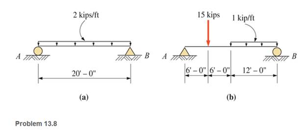
Chapter 13, Problem 13.8P
Calculate the shear and bending moment at 3 ft and at 8 ft from the left for the beams shown. Show free-body diagrams.
Expert Solution & Answer

Learn your wayIncludes step-by-step video

schedule04:59
Students have asked these similar questions
For the beam shown below, provide equations at each section. Draw the shear and moment diagram of the beam on the space provided below.
Plot the shear and moment diagrams for the beam loaded with both distributed and point loads.What is the value of the bending moment at x = 7 m?
Calculate the shear force and bending moment for the simply supported beam of length 8m
with the self-weight of 1OKN given below. Also draw the shear force and bending moment
diagrams.
6 kN
5 kN
4 kN
1m
2m
3m
Chapter 13 Solutions
Applied Statics and Strength of Materials (6th Edition)
Ch. 13 - through 13.6 Calculate the reactions at points A...Ch. 13 - Calculate the reactions at points A and B for the...Ch. 13 - through 13.6 Calculate the reactions at points A...Ch. 13 - Calculate the reactions at points A and B for the...Ch. 13 - Calculate the reactions at points A and B for the...Ch. 13 - Calculate the reactions at points A and B for the...Ch. 13 - Calculate the shear and bending moment at 4 m and...Ch. 13 - Calculate the shear and bending moment at 3 ft and...Ch. 13 - Calculate the shear and bending moment at midspan...Ch. 13 - Calculate the shear and bending moment at 5 ft and...
Ch. 13 - Calculate the shear and bending moment at 5 m and...Ch. 13 - For the beams shown, draw complete shear diagrams.Ch. 13 - For the beams shown, draw complete shear diagrams.Ch. 13 - Prob. 13.14PCh. 13 - For the beams shown, draw complete shear diagrams.Ch. 13 - For the beams shown (next page), draw complete...Ch. 13 - For the beams shown (next page), draw complete...Ch. 13 - For the beams shown (next page), draw complete...Ch. 13 - For the beams shown (next page), draw complete...Ch. 13 - For the beams shown (next page), draw complete...Ch. 13 - For the beams shown, draw complete shear and...Ch. 13 - For the beams shown, draw complete shear and...Ch. 13 - For the beams shown, draw complete shear and...Ch. 13 - A moving-load system is composed of two...Ch. 13 - A moving-load system is composed of two...Ch. 13 - One of the standard truck loads used in the design...Ch. 13 - Write a computer program that will calculate the...Ch. 13 - Write a program that will calculate the shear and...Ch. 13 - Viking Consultants wishes to generate a table of...Ch. 13 - Calculate the reactions for the simple beams...Ch. 13 - Calculate the reactions for the overhanging beams...Ch. 13 - Calculate the reactions at points A and B for the...Ch. 13 - Calculate the reactions at points A and B for the...Ch. 13 - For the beams of Problem 13.33, calculate the...Ch. 13 - For the beam shown, calculate the shear and...Ch. 13 - Calculate the shear and bending moment at points 4...Ch. 13 - Calculate the shear arid bending moment at points...Ch. 13 - Calculate the shear and bending moment at points...Ch. 13 - Refer to the beam shown and draw complete shear...Ch. 13 - Refer to the beam shown and draw complete shear...Ch. 13 - Refer to the beam shown and draw complete shear...Ch. 13 - Refer to the beam shown and draw complete shear...Ch. 13 - Refer to the beam shown and draw complete shear...Ch. 13 - Refer to the beam shown and draw complete shear...Ch. 13 - Refer to the beam shown and draw complete shear...Ch. 13 - Refer to the beam shown and draw complete shear...Ch. 13 - Refer to the beam shown and draw complete shear...Ch. 13 - Refer to the indicated problem and draw complete...Ch. 13 - Refer to the indicated problem and draw complete...Ch. 13 - Refer to the indicated problem and draw complete...Ch. 13 - Refer to the indicated problem and draw complete...Ch. 13 - Refer to the indicated problem and draw complete...Ch. 13 - Refer to the indicated problem and draw complete...Ch. 13 - Refer to the indicated problem and draw complete...Ch. 13 - Refer to the indicated problem and draw complete...Ch. 13 - Refer to the indicated problem and draw complete...Ch. 13 - Refer to the indicated problem and draw complete...Ch. 13 - Refer to the indicated problem and draw complete...Ch. 13 - A two-axle roller with axles 5 m apart passes over...Ch. 13 - A moving load system with wheels at fixed...Ch. 13 - A moving-load system with wheels spaced as shown...
Additional Engineering Textbook Solutions
Find more solutions based on key concepts
What parts are included in the vehicle chassis?
Automotive Technology: Principles, Diagnosis, and Service (5th Edition)
The rigid bar is supported by the pin-connected rod CB that has a cross-sectional area of 14 mm2 and is made fr...
Mechanics of Materials (10th Edition)
ICA 13-22
As a reminder, the Reynolds number is discussed in Chapter 9. Dimensionless Number.
When discussing t...
Thinking Like an Engineer: An Active Learning Approach (3rd Edition)
Figure 8.12shows a portion of a fire protection system in which a pump draws water at 60 F from a reservoir and...
Applied Fluid Mechanics (7th Edition)
Determine the displacement at point C. El is constant. Prob. 1487
Mechanics of Materials
Determine the maximum mass of the crate so that the tension developed in any cable does not exceeded 3 kN.
INTERNATIONAL EDITION---Engineering Mechanics: Statics, 14th edition (SI unit)
Knowledge Booster


Learn more about
Need a deep-dive on the concept behind this application? Look no further. Learn more about this topic, mechanical-engineering and related others by exploring similar questions and additional content below.Similar questions
- Draw the Shear force and bending moment diagram for the beam as shown in figure.arrow_forwardDraw the shear and bending moment diagram for the following beam and indicate the values of the maximum shear and maximum moment. Need free body diagramsarrow_forwardFor the beam shown, calculate the shear and bending moment at points 6 ft and 16 ft from the left end using free-body diagrams. Also draw shear and bending diagramarrow_forward
- What is the maximum intensity of moment for the beam loaded as shown? What is the magnitude of R2? What is the shear value at point just before C? What is the magnitude of R1?arrow_forwardFor the beam shown, derive the expressions for V and M, and draw the shear force and bending moment diagrams. Calculate the shear force V and bending moment M at a cross section located 0.5 m from the fixed support. Neglect the weight of the beam. (Show complete calculation and step by step process. Show free body diagram)arrow_forwardDraw the shear force and bending moment diagrams for the beam shown in your solution sheets. Determine the maximum positive shear force in kips. Determine the maximum negative shear force in kips. Determine the maximum positive bending moment in kip-ft. Determine the maximum negative bending moment in kip-ft.* Determine the point of inflection from point C in feet.arrow_forward
- Shear and moment in beams Draw the shear-force and bending-moment diagrams for the beam shown. Determine the maximum shear and maximum bending moment that occur in the span. provide detailed solutionarrow_forwardCalculate the bending moment at points A and B for the beam shown below. 5 kN 2.5 kN/m A 1.5 m 4 marrow_forwardFor the beam shown on the picture select the corresponding shear force and bending moment diagrams from belowarrow_forward
arrow_back_ios
SEE MORE QUESTIONS
arrow_forward_ios
Recommended textbooks for you
 Elements Of ElectromagneticsMechanical EngineeringISBN:9780190698614Author:Sadiku, Matthew N. O.Publisher:Oxford University Press
 Mechanics of Materials (10th Edition)Mechanical EngineeringISBN:9780134319650Author:Russell C. HibbelerPublisher:PEARSON
 Thermodynamics: An Engineering ApproachMechanical EngineeringISBN:9781259822674Author:Yunus A. Cengel Dr., Michael A. BolesPublisher:McGraw-Hill Education
 Control Systems EngineeringMechanical EngineeringISBN:9781118170519Author:Norman S. NisePublisher:WILEY
 Mechanics of Materials (MindTap Course List)Mechanical EngineeringISBN:9781337093347Author:Barry J. Goodno, James M. GerePublisher:Cengage Learning
 Engineering Mechanics: StaticsMechanical EngineeringISBN:9781118807330Author:James L. Meriam, L. G. Kraige, J. N. BoltonPublisher:WILEY
Elements Of Electromagnetics
Mechanical Engineering
ISBN:9780190698614
Author:Sadiku, Matthew N. O.
Publisher:Oxford University Press
Mechanics of Materials (10th Edition)
Mechanical Engineering
ISBN:9780134319650
Author:Russell C. Hibbeler
Publisher:PEARSON
Thermodynamics: An Engineering Approach
Mechanical Engineering
ISBN:9781259822674
Author:Yunus A. Cengel Dr., Michael A. Boles
Publisher:McGraw-Hill Education
Control Systems Engineering
Mechanical Engineering
ISBN:9781118170519
Author:Norman S. Nise
Publisher:WILEY
Mechanics of Materials (MindTap Course List)
Mechanical Engineering
ISBN:9781337093347
Author:Barry J. Goodno, James M. Gere
Publisher:Cengage Learning
Engineering Mechanics: Statics
Mechanical Engineering
ISBN:9781118807330
Author:James L. Meriam, L. G. Kraige, J. N. Bolton
Publisher:WILEY
Understanding Shear Force and Bending Moment Diagrams; Author: The Efficient Engineer;https://www.youtube.com/watch?v=C-FEVzI8oe8;License: Standard YouTube License, CC-BY
Bending Stress; Author: moodlemech;https://www.youtube.com/watch?v=9QIqewkE6xM;License: Standard Youtube License