
Applied Statics and Strength of Materials (6th Edition)
6th Edition
ISBN: 9780133840544
Author: George F. Limbrunner, Craig D'Allaird, Leonard Spiegel
Publisher: PEARSON
expand_more
expand_more
format_list_bulleted
Concept explainers
Videos
Textbook Question
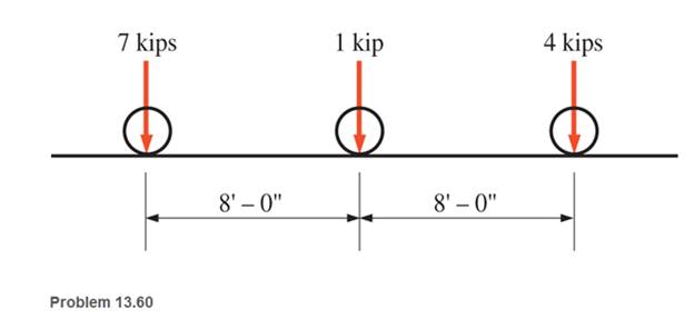
Chapter 13, Problem 13.60SP
A moving load system with wheels at fixed distances apart as shown crosses a 40-ft simply supported beam bridge. Compute the absolute maximum moment and shear.
Expert Solution & Answer
Want to see the full answer?
Check out a sample textbook solution
Students have asked these similar questions
Draw the bending moment and shear diagrams for bar CD of the structure below.
For the beams below, draw the shear and bending moment diagrams using both method
of sections and area method. Determine the absolute maximum values of the shear and
bending moment and indicate the degree of each curve. For problems 2 and 3, note that
there are internal hinges at C and B, respectively.
Problem 1
Problem 2
50 kN 40 kN/m
20 KN/m
50 Ib
50 kN
25 lb/ft
15 Ib/ft
200 kN-m
10 ft-
5 ft 5 ft
-10 ft 5 ft -
100 kN
2 m--im
-3 m-
Answer:
140 kN
Vmax
Mmax = 462.5 kN-m
Answer:
Vmax
Mmax = 4250 lb-ft
487.5 lb
тах
Calculate the shear force and bending moment for the simply supported beam of length 8m
with the self-weight of 1OKN given below. Also draw the shear force and bending moment
diagrams.
6 kN
5 kN
4 kN
1m
2m
3m
Chapter 13 Solutions
Applied Statics and Strength of Materials (6th Edition)
Ch. 13 - through 13.6 Calculate the reactions at points A...Ch. 13 - Calculate the reactions at points A and B for the...Ch. 13 - through 13.6 Calculate the reactions at points A...Ch. 13 - Calculate the reactions at points A and B for the...Ch. 13 - Calculate the reactions at points A and B for the...Ch. 13 - Calculate the reactions at points A and B for the...Ch. 13 - Calculate the shear and bending moment at 4 m and...Ch. 13 - Calculate the shear and bending moment at 3 ft and...Ch. 13 - Calculate the shear and bending moment at midspan...Ch. 13 - Calculate the shear and bending moment at 5 ft and...
Ch. 13 - Calculate the shear and bending moment at 5 m and...Ch. 13 - For the beams shown, draw complete shear diagrams.Ch. 13 - For the beams shown, draw complete shear diagrams.Ch. 13 - Prob. 13.14PCh. 13 - For the beams shown, draw complete shear diagrams.Ch. 13 - For the beams shown (next page), draw complete...Ch. 13 - For the beams shown (next page), draw complete...Ch. 13 - For the beams shown (next page), draw complete...Ch. 13 - For the beams shown (next page), draw complete...Ch. 13 - For the beams shown (next page), draw complete...Ch. 13 - For the beams shown, draw complete shear and...Ch. 13 - For the beams shown, draw complete shear and...Ch. 13 - For the beams shown, draw complete shear and...Ch. 13 - A moving-load system is composed of two...Ch. 13 - A moving-load system is composed of two...Ch. 13 - One of the standard truck loads used in the design...Ch. 13 - Write a computer program that will calculate the...Ch. 13 - Write a program that will calculate the shear and...Ch. 13 - Viking Consultants wishes to generate a table of...Ch. 13 - Calculate the reactions for the simple beams...Ch. 13 - Calculate the reactions for the overhanging beams...Ch. 13 - Calculate the reactions at points A and B for the...Ch. 13 - Calculate the reactions at points A and B for the...Ch. 13 - For the beams of Problem 13.33, calculate the...Ch. 13 - For the beam shown, calculate the shear and...Ch. 13 - Calculate the shear and bending moment at points 4...Ch. 13 - Calculate the shear arid bending moment at points...Ch. 13 - Calculate the shear and bending moment at points...Ch. 13 - Refer to the beam shown and draw complete shear...Ch. 13 - Refer to the beam shown and draw complete shear...Ch. 13 - Refer to the beam shown and draw complete shear...Ch. 13 - Refer to the beam shown and draw complete shear...Ch. 13 - Refer to the beam shown and draw complete shear...Ch. 13 - Refer to the beam shown and draw complete shear...Ch. 13 - Refer to the beam shown and draw complete shear...Ch. 13 - Refer to the beam shown and draw complete shear...Ch. 13 - Refer to the beam shown and draw complete shear...Ch. 13 - Refer to the indicated problem and draw complete...Ch. 13 - Refer to the indicated problem and draw complete...Ch. 13 - Refer to the indicated problem and draw complete...Ch. 13 - Refer to the indicated problem and draw complete...Ch. 13 - Refer to the indicated problem and draw complete...Ch. 13 - Refer to the indicated problem and draw complete...Ch. 13 - Refer to the indicated problem and draw complete...Ch. 13 - Refer to the indicated problem and draw complete...Ch. 13 - Refer to the indicated problem and draw complete...Ch. 13 - Refer to the indicated problem and draw complete...Ch. 13 - Refer to the indicated problem and draw complete...Ch. 13 - A two-axle roller with axles 5 m apart passes over...Ch. 13 - A moving load system with wheels at fixed...Ch. 13 - A moving-load system with wheels spaced as shown...
Knowledge Booster


Learn more about
Need a deep-dive on the concept behind this application? Look no further. Learn more about this topic, mechanical-engineering and related others by exploring similar questions and additional content below.Similar questions
- For the beam and its shear diagram shown below, the distance x is measured from the left end of the beam. The maximum moment occurs where x is ?arrow_forwardA simply supported beam of 7 m span with overhangs rests on supports which are 4 m apart. The left end overhanging is 2 m. The beam carries loads of 30 kN and 20 kN on the left and the right ends respectively apart from a uniformly distributed load of 25 kN/m between the supporting points. Draw the shear force and bending moment diagrams.arrow_forwardCalculate the shear force V at the midpoint of the beamarrow_forward
- Determine the shear force, V and its bending moment, M. kindly provide the SFD and BMDarrow_forwardEngineer Abella's brand new van is about to cross a 15-meter bridge. Each axle has P1= 30 kN, P2= 60 kN, and P3= 50 kN loads respectively. The distance of P1 and P2 is 7 m and P3 is 4 meters away from P2. Compute the maximum moment and maximum shear developed in the span.arrow_forwardDraw the shear force diagram and moment diagram for beam loaded as shown. P/ N/m Parrow_forward
- Draw the bending moment and shear diagrams for the beam and loading shown below. Use the summation method.arrow_forwardSHEAR AND MOMENT DIAGRAM PROBLEM 2 Use the AREA method to construct the shear-force and bending-moment diagrams for the beam shown. Let a = 6.9 ft, b = 10.4 ft, c = 5.8 ft, and w = 9.5 kips/ft. Label all significant points on each diagram and identify the maximum moments (both positive and negative) along with their respective locations. Clearly differentiate straight-line and curved portions of the diagrams. Determine the maximum shear force and bending moment in the beam. Note that answers may be positive or negative. Here, "maximum" refers to the largest magnitude value, but you should enter your shear force and bending moment with the correct sign, using the sign convention. If the magnitudes of the largest positive and largest negative values are the same, enter a positive number. The roller at point D indicates that motion is restricted both up and down, and the beam will not lift off the roller. a B W b O D Xarrow_forwardSHEAR AND MOMENT DIAGRAM PROBLEM 2 Use the AREA method to construct the shear-force and bending-moment diagrams for the beam shown. Let a = 6.9 ft, b = 10.4 ft, c = 5.8 ft, and w = 9.5 kips/ft. Label all significant points on each diagram and identify the maximum moments (both positive and negative) along with their respective locations. Clearly differentiate straight-line and curved portions of the diagrams. Determine the maximum shear force and bending moment in the beam. Note that answers may be positive or negative. Here, "maximum" refers to the largest magnitude value, but you should enter your shear force and bending moment with the correct sign, using the sign convention. If the magnitudes of the largest positive and largest negative values are the same, enter a positive number. The roller at point D indicates that motion is restricted both up and down, and the beam will not lift off the roller. a B W b C D Xarrow_forward
- A simply supported beam, 50mm wide by 100mm high and 300 mm long is subjected to a concentrated load of 3000 N at a point 100 mm from one of the supports. Draw the shear force and bending moment diagrams for the beam.arrow_forwardDraw the shearing force and bending moment diagrams for the beam with an overhang subjected to the loads shown.arrow_forwardThe structure shown consists of a rolled-steel beam AB and two short members welded together to the beam. Solve the shear and bending moment functions for values of W and Parrow_forward
arrow_back_ios
SEE MORE QUESTIONS
arrow_forward_ios
Recommended textbooks for you
 Elements Of ElectromagneticsMechanical EngineeringISBN:9780190698614Author:Sadiku, Matthew N. O.Publisher:Oxford University Press
 Mechanics of Materials (10th Edition)Mechanical EngineeringISBN:9780134319650Author:Russell C. HibbelerPublisher:PEARSON
 Thermodynamics: An Engineering ApproachMechanical EngineeringISBN:9781259822674Author:Yunus A. Cengel Dr., Michael A. BolesPublisher:McGraw-Hill Education
 Control Systems EngineeringMechanical EngineeringISBN:9781118170519Author:Norman S. NisePublisher:WILEY
 Mechanics of Materials (MindTap Course List)Mechanical EngineeringISBN:9781337093347Author:Barry J. Goodno, James M. GerePublisher:Cengage Learning
 Engineering Mechanics: StaticsMechanical EngineeringISBN:9781118807330Author:James L. Meriam, L. G. Kraige, J. N. BoltonPublisher:WILEY
Elements Of Electromagnetics
Mechanical Engineering
ISBN:9780190698614
Author:Sadiku, Matthew N. O.
Publisher:Oxford University Press
Mechanics of Materials (10th Edition)
Mechanical Engineering
ISBN:9780134319650
Author:Russell C. Hibbeler
Publisher:PEARSON
Thermodynamics: An Engineering Approach
Mechanical Engineering
ISBN:9781259822674
Author:Yunus A. Cengel Dr., Michael A. Boles
Publisher:McGraw-Hill Education
Control Systems Engineering
Mechanical Engineering
ISBN:9781118170519
Author:Norman S. Nise
Publisher:WILEY
Mechanics of Materials (MindTap Course List)
Mechanical Engineering
ISBN:9781337093347
Author:Barry J. Goodno, James M. Gere
Publisher:Cengage Learning
Engineering Mechanics: Statics
Mechanical Engineering
ISBN:9781118807330
Author:James L. Meriam, L. G. Kraige, J. N. Bolton
Publisher:WILEY
Understanding Shear Force and Bending Moment Diagrams; Author: The Efficient Engineer;https://www.youtube.com/watch?v=C-FEVzI8oe8;License: Standard YouTube License, CC-BY
Bending Stress; Author: moodlemech;https://www.youtube.com/watch?v=9QIqewkE6xM;License: Standard Youtube License