
Applied Statics and Strength of Materials (6th Edition)
6th Edition
ISBN: 9780133840544
Author: George F. Limbrunner, Craig D'Allaird, Leonard Spiegel
Publisher: PEARSON
expand_more
expand_more
format_list_bulleted
Concept explainers
Videos
Textbook Question
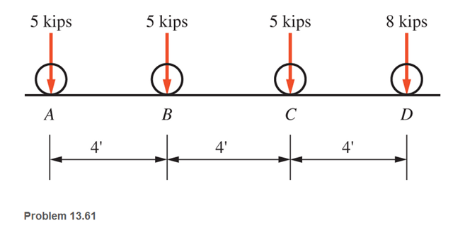
Chapter 13, Problem 13.61SP
A moving-load system with wheels spaced as shown crosses a 40-ft, single span, simply supported beam bridge. Compute
a. the maximum moment under wheel C
b. the maximum moment under wheel D
c. the absolute maximum shear
Expert Solution & Answer
Want to see the full answer?
Check out a sample textbook solution
Students have asked these similar questions
Problem #5: For the 2D beam below, with F 15 kips, M, = 7 kip-ft, and
shear and bending moment diagrams. Report your answer in kip and kip-ft to one decimal place.
w,= 2.5 kip/ft draw the
Wo
F,
Fo
Mo
Mo
2.0 ft
1.0 ft
5.0 ft
2.0 ft
Use the graphical method to construct the shear-force and bending-moment diagrams for the beam shown. Let a=4.0 m, b=2.5 m, PB = 4 kN, PC = 4 kN, and MB = 60 kN-m. Construct the shear-force and bending-moment diagrams on paper and use the results to answer the questions in the subsequent parts of this GO exercise.Calculate the reaction forces Ay and MA acting on the beam. Positive values for the reactions are indicated by the directions of the red arrows shown on the free-body diagram below. (Note: Since Ax = 0, it has been omitted from the free-body diagram.)Answers: Ay = kN, MA = kN-m.
Use the graphical method to construct the shear-force and bending-moment diagrams for the beam shown. Let a=4.0 m, b=2.5 m, PB = 4 kN, PC = 4 kN, and MB = 60 kN-m. Construct the shear-force and bending-moment diagrams on paper and use the results to answer the questions in the subsequent parts of this GO exercise.Calculate the reaction forces Ay and MA acting on the beam. Positive values for the reactions are indicated by the directions of the red arrows shown on the free-body diagram below. (Note: Since Ax = 0, it has been omitted from the free-body diagram.)
Determine the bending moment acting at each of the following locations:(a) x = 0+ m (i.e., just to the right of fixed support A)(b) x = 4.0– m (i.e., just to the left of B)(c) x = 4.0+ m (i.e., just to the right of B)(d) x = 6.5 mWhen entering your answers, use the bending moment sign convention.Answers:(a) M = kN-m.(b) M = kN-m.(c) M = kN-m.(d) M = kN-m.
Chapter 13 Solutions
Applied Statics and Strength of Materials (6th Edition)
Ch. 13 - through 13.6 Calculate the reactions at points A...Ch. 13 - Calculate the reactions at points A and B for the...Ch. 13 - through 13.6 Calculate the reactions at points A...Ch. 13 - Calculate the reactions at points A and B for the...Ch. 13 - Calculate the reactions at points A and B for the...Ch. 13 - Calculate the reactions at points A and B for the...Ch. 13 - Calculate the shear and bending moment at 4 m and...Ch. 13 - Calculate the shear and bending moment at 3 ft and...Ch. 13 - Calculate the shear and bending moment at midspan...Ch. 13 - Calculate the shear and bending moment at 5 ft and...
Ch. 13 - Calculate the shear and bending moment at 5 m and...Ch. 13 - For the beams shown, draw complete shear diagrams.Ch. 13 - For the beams shown, draw complete shear diagrams.Ch. 13 - Prob. 13.14PCh. 13 - For the beams shown, draw complete shear diagrams.Ch. 13 - For the beams shown (next page), draw complete...Ch. 13 - For the beams shown (next page), draw complete...Ch. 13 - For the beams shown (next page), draw complete...Ch. 13 - For the beams shown (next page), draw complete...Ch. 13 - For the beams shown (next page), draw complete...Ch. 13 - For the beams shown, draw complete shear and...Ch. 13 - For the beams shown, draw complete shear and...Ch. 13 - For the beams shown, draw complete shear and...Ch. 13 - A moving-load system is composed of two...Ch. 13 - A moving-load system is composed of two...Ch. 13 - One of the standard truck loads used in the design...Ch. 13 - Write a computer program that will calculate the...Ch. 13 - Write a program that will calculate the shear and...Ch. 13 - Viking Consultants wishes to generate a table of...Ch. 13 - Calculate the reactions for the simple beams...Ch. 13 - Calculate the reactions for the overhanging beams...Ch. 13 - Calculate the reactions at points A and B for the...Ch. 13 - Calculate the reactions at points A and B for the...Ch. 13 - For the beams of Problem 13.33, calculate the...Ch. 13 - For the beam shown, calculate the shear and...Ch. 13 - Calculate the shear and bending moment at points 4...Ch. 13 - Calculate the shear arid bending moment at points...Ch. 13 - Calculate the shear and bending moment at points...Ch. 13 - Refer to the beam shown and draw complete shear...Ch. 13 - Refer to the beam shown and draw complete shear...Ch. 13 - Refer to the beam shown and draw complete shear...Ch. 13 - Refer to the beam shown and draw complete shear...Ch. 13 - Refer to the beam shown and draw complete shear...Ch. 13 - Refer to the beam shown and draw complete shear...Ch. 13 - Refer to the beam shown and draw complete shear...Ch. 13 - Refer to the beam shown and draw complete shear...Ch. 13 - Refer to the beam shown and draw complete shear...Ch. 13 - Refer to the indicated problem and draw complete...Ch. 13 - Refer to the indicated problem and draw complete...Ch. 13 - Refer to the indicated problem and draw complete...Ch. 13 - Refer to the indicated problem and draw complete...Ch. 13 - Refer to the indicated problem and draw complete...Ch. 13 - Refer to the indicated problem and draw complete...Ch. 13 - Refer to the indicated problem and draw complete...Ch. 13 - Refer to the indicated problem and draw complete...Ch. 13 - Refer to the indicated problem and draw complete...Ch. 13 - Refer to the indicated problem and draw complete...Ch. 13 - Refer to the indicated problem and draw complete...Ch. 13 - A two-axle roller with axles 5 m apart passes over...Ch. 13 - A moving load system with wheels at fixed...Ch. 13 - A moving-load system with wheels spaced as shown...
Knowledge Booster


Learn more about
Need a deep-dive on the concept behind this application? Look no further. Learn more about this topic, mechanical-engineering and related others by exploring similar questions and additional content below.Similar questions
- Use the graphical method to construct the shear-force and bending-moment diagrams for the beam shown. Let a=4.0 m, b=2.5 m, PB = 4 kN, PC = 4 kN, and MB = 60 kN-m. Construct the shear-force and bending-moment diagrams on paper and use the results to answer the questions in the subsequent parts of this GO exercise.Calculate the reaction forces Ay and MA acting on the beam. Positive values for the reactions are indicated by the directions of the red arrows shown on the free-body diagram below. (Note: Since Ax = 0, it has been omitted from the free-body diagram.)Answers: Ay = kN, MA = kN-m. Determine the shear force acting at each of the following locations:(a) x = 0+ m (i.e., just to the right of fixed support A)(b) x = 4.0– m (i.e., just to the left of B)(c) x = 4.0+ m (i.e., just to the right of B)(d) x = 6.5– m (i.e., just to the left of C)When entering your answers, use the shear force sign convention.Answer:(a) V = kN.(b) V = kN.(c) V = kN.(d) V = kN.arrow_forwardFor the figure shown below, compute the bending moment in section 1. Neglect the weights of the member. Note that point B is pin-connected. 50KN ... 2m 5m 60° 5m 5marrow_forwardA cantilever beam of length 2 m carries the point loads as shown in Fig. Draw the shear force and B.M. diagrams for the cantilever beam with necessary calculation.arrow_forward
- Use the graphical method to construct the shear-force and bending-moment diagrams for the beam shown. Let a=3.5 m, b=5.0 m, Mg = 60 kN-m and Mc = 85 kN-m. Construct the shear-force and bending-moment diagrams on paper and use the results to answer the questions in the subsequent parts of this GO exercise. MB Mc D. Calculate the reaction forces A, and Dy acting on the beam. Positive values for the reactions are indicated by the directions of the red arrows shown on the free-body diagram below. (Note: Since A = 0, it has been omitted from the free-body diagram.) Mg D D, Answers: Ay = i kN, Dy = kN.arrow_forwardPART 1 Use the graphical method to construct the shear-force and bending-moment diagrams for the beam shown. Let a=3.5 m, b=2.0 m, PB = 2 kN, PC = 2 kN, and MB = 20 kN-m. Construct the shear-force and bending-moment diagrams on paper and use the results to answer the questions in the subsequent parts of this GO exercise. IMAGE* Calculate the reaction forces Ay and MA acting on the beam. Positive values for the reactions are indicated by the directions of the red arrows shown on the free-body diagram below. (Note: Since Ax = 0, it has been omitted from the free-body diagram.) IMAGE* PART 2 Determine the shear force acting at each of the following locations:(a) x = 0+ m (i.e., just to the right of fixed support A)(b) x = 3.5– m (i.e., just to the left of B)(c) x = 3.5+ m (i.e., just to the right of B)(d) x = 5.5– m (i.e., just to the left of C)When entering your answers, use the shear force sign convention.Answer:(a) V = ? kN.(b) V = ? kN.(c) V = ? kN.(d) V = ? kN. PART 3…arrow_forwardDraw the bending moment and shear diagrams for bar CD of the structure below.arrow_forward
- For the beams below, draw the shear and bending moment diagrams using both method of sections and area method. Determine the absolute maximum values of the shear and bending moment and indicate the degree of each curve. For problems 2 and 3, note that there are internal hinges at C and B, respectively. Problem 1 Problem 2 50 kN 40 kN/m 20 KN/m 50 Ib 50 kN 25 lb/ft 15 Ib/ft 200 kN-m 10 ft- 5 ft 5 ft -10 ft 5 ft - 100 kN 2 m--im -3 m- Answer: 140 kN Vmax Mmax = 462.5 kN-m Answer: Vmax Mmax = 4250 lb-ft 487.5 lb тахarrow_forwardCalculate the reactions at the supports and obtain the shear force and bending moment diagrams for the following shaft using MD Solids software. The diameter of the shaft is 3.5433 inches and FA = 84.80 pounds-force.arrow_forwardThe beam shown carries a uniformly distributed load of 2 kN/m along span BC. The beam is supported by a roller at B and pin-connected at C. 2 kN/m 6 kN 6 kN a. Compute for the slope at B using the conjugate beam method. b. Compute the displacement of A using the conjugate beam method. c. Compute the displacement of A using the moment area method.arrow_forward
- 3. A simply supported beam of length 8 m carries point loads of 4 kN, 10 kN and 7 kN at 1.5 m, 2.5 m and 2 m respectively from left end A. Draw the S.F. and B.M. diagrams for the simply supported beam.arrow_forwardFor the simply supported beam subjected to the loading shown, derive equations for the shear force Vand the bending moment M for any location in the beam. (Place the origin at point A.) Let w = 19.0 kips/ft, a=5.0 ft, and b=15.5 ft. Construct the shear-force and bending-moment diagrams on paper and use the results to answer the questions in the subsequent parts of this GO exercise. b Calculate the reaction forces By and Cy acting on the beam. Positive values for the reactions are indicated by the directions of the red arrows shown on the free-body diagram below. (Note: Since Bx = 0, it has been omitted from the free-body diagram.) a b By |C, Answers: By = i kips Cy = i kips Determine the shear force acting at each of the following locations: (a) x = 5.0- ft (i.e., just to the left of support B) (b) x = 5.0+ ft (i.e., just to the right of support B) (c) x = 19.5 ft (d) x = 20.5- ft (i.e., just to the left of support C) Note that x = 0 at point A. When entering your answers, use the…arrow_forwardtruck and trailer combination crossing a 16-m span has axle loads of 10, 20, and 30 kN separated respectively by distances of 3 and 5 m. Compute the maximum moment and maximum shear developed in the span.arrow_forward
arrow_back_ios
SEE MORE QUESTIONS
arrow_forward_ios
Recommended textbooks for you
 Elements Of ElectromagneticsMechanical EngineeringISBN:9780190698614Author:Sadiku, Matthew N. O.Publisher:Oxford University Press
 Mechanics of Materials (10th Edition)Mechanical EngineeringISBN:9780134319650Author:Russell C. HibbelerPublisher:PEARSON
 Thermodynamics: An Engineering ApproachMechanical EngineeringISBN:9781259822674Author:Yunus A. Cengel Dr., Michael A. BolesPublisher:McGraw-Hill Education
 Control Systems EngineeringMechanical EngineeringISBN:9781118170519Author:Norman S. NisePublisher:WILEY
 Mechanics of Materials (MindTap Course List)Mechanical EngineeringISBN:9781337093347Author:Barry J. Goodno, James M. GerePublisher:Cengage Learning
 Engineering Mechanics: StaticsMechanical EngineeringISBN:9781118807330Author:James L. Meriam, L. G. Kraige, J. N. BoltonPublisher:WILEY
Elements Of Electromagnetics
Mechanical Engineering
ISBN:9780190698614
Author:Sadiku, Matthew N. O.
Publisher:Oxford University Press
Mechanics of Materials (10th Edition)
Mechanical Engineering
ISBN:9780134319650
Author:Russell C. Hibbeler
Publisher:PEARSON
Thermodynamics: An Engineering Approach
Mechanical Engineering
ISBN:9781259822674
Author:Yunus A. Cengel Dr., Michael A. Boles
Publisher:McGraw-Hill Education
Control Systems Engineering
Mechanical Engineering
ISBN:9781118170519
Author:Norman S. Nise
Publisher:WILEY
Mechanics of Materials (MindTap Course List)
Mechanical Engineering
ISBN:9781337093347
Author:Barry J. Goodno, James M. Gere
Publisher:Cengage Learning
Engineering Mechanics: Statics
Mechanical Engineering
ISBN:9781118807330
Author:James L. Meriam, L. G. Kraige, J. N. Bolton
Publisher:WILEY
Understanding Shear Force and Bending Moment Diagrams; Author: The Efficient Engineer;https://www.youtube.com/watch?v=C-FEVzI8oe8;License: Standard YouTube License, CC-BY
Bending Stress; Author: moodlemech;https://www.youtube.com/watch?v=9QIqewkE6xM;License: Standard Youtube License