
Applied Statics and Strength of Materials (6th Edition)
6th Edition
ISBN: 9780133840544
Author: George F. Limbrunner, Craig D'Allaird, Leonard Spiegel
Publisher: PEARSON
expand_more
expand_more
format_list_bulleted
Concept explainers
Videos
Textbook Question
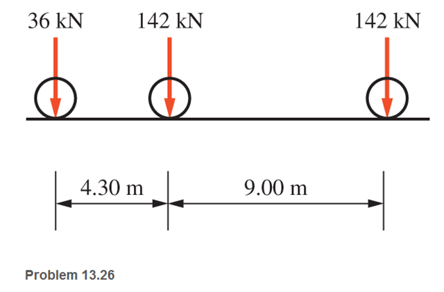
Chapter 13, Problem 13.26P
One of the standard truck loads used in the design of bridges is composed of three concentrated loads, as shown. Calculate the absolute maximum shear and moment produced in a simple bridge span having a length of 26 m.
Expert Solution & Answer

Trending nowThis is a popular solution!

Students have asked these similar questions
The simply supported beam shown below has distributed load that increases linearly from OkN/m at
the centre of the beam to 8kN/m at the right hand end. Determine the reaction forces and plot the
bending moment and shear force diagrams.
1.5 m
1.5 m
8 kN/m
Engineer Abella's brand new van is about to cross a 15-meter bridge. Each axle has P1= 30 kN, P2= 60 kN, and P3= 50 kN loads respectively. The distance of P1 and P2 is 7 m and P3 is 4 meters away from P2. Compute the maximum moment and maximum shear developed in the span.
Draw the shear force and bending moment diagrams for the following structure. Clearly indicate the location and maximum magnitude of the shear and moment
Chapter 13 Solutions
Applied Statics and Strength of Materials (6th Edition)
Ch. 13 - through 13.6 Calculate the reactions at points A...Ch. 13 - Calculate the reactions at points A and B for the...Ch. 13 - through 13.6 Calculate the reactions at points A...Ch. 13 - Calculate the reactions at points A and B for the...Ch. 13 - Calculate the reactions at points A and B for the...Ch. 13 - Calculate the reactions at points A and B for the...Ch. 13 - Calculate the shear and bending moment at 4 m and...Ch. 13 - Calculate the shear and bending moment at 3 ft and...Ch. 13 - Calculate the shear and bending moment at midspan...Ch. 13 - Calculate the shear and bending moment at 5 ft and...
Ch. 13 - Calculate the shear and bending moment at 5 m and...Ch. 13 - For the beams shown, draw complete shear diagrams.Ch. 13 - For the beams shown, draw complete shear diagrams.Ch. 13 - Prob. 13.14PCh. 13 - For the beams shown, draw complete shear diagrams.Ch. 13 - For the beams shown (next page), draw complete...Ch. 13 - For the beams shown (next page), draw complete...Ch. 13 - For the beams shown (next page), draw complete...Ch. 13 - For the beams shown (next page), draw complete...Ch. 13 - For the beams shown (next page), draw complete...Ch. 13 - For the beams shown, draw complete shear and...Ch. 13 - For the beams shown, draw complete shear and...Ch. 13 - For the beams shown, draw complete shear and...Ch. 13 - A moving-load system is composed of two...Ch. 13 - A moving-load system is composed of two...Ch. 13 - One of the standard truck loads used in the design...Ch. 13 - Write a computer program that will calculate the...Ch. 13 - Write a program that will calculate the shear and...Ch. 13 - Viking Consultants wishes to generate a table of...Ch. 13 - Calculate the reactions for the simple beams...Ch. 13 - Calculate the reactions for the overhanging beams...Ch. 13 - Calculate the reactions at points A and B for the...Ch. 13 - Calculate the reactions at points A and B for the...Ch. 13 - For the beams of Problem 13.33, calculate the...Ch. 13 - For the beam shown, calculate the shear and...Ch. 13 - Calculate the shear and bending moment at points 4...Ch. 13 - Calculate the shear arid bending moment at points...Ch. 13 - Calculate the shear and bending moment at points...Ch. 13 - Refer to the beam shown and draw complete shear...Ch. 13 - Refer to the beam shown and draw complete shear...Ch. 13 - Refer to the beam shown and draw complete shear...Ch. 13 - Refer to the beam shown and draw complete shear...Ch. 13 - Refer to the beam shown and draw complete shear...Ch. 13 - Refer to the beam shown and draw complete shear...Ch. 13 - Refer to the beam shown and draw complete shear...Ch. 13 - Refer to the beam shown and draw complete shear...Ch. 13 - Refer to the beam shown and draw complete shear...Ch. 13 - Refer to the indicated problem and draw complete...Ch. 13 - Refer to the indicated problem and draw complete...Ch. 13 - Refer to the indicated problem and draw complete...Ch. 13 - Refer to the indicated problem and draw complete...Ch. 13 - Refer to the indicated problem and draw complete...Ch. 13 - Refer to the indicated problem and draw complete...Ch. 13 - Refer to the indicated problem and draw complete...Ch. 13 - Refer to the indicated problem and draw complete...Ch. 13 - Refer to the indicated problem and draw complete...Ch. 13 - Refer to the indicated problem and draw complete...Ch. 13 - Refer to the indicated problem and draw complete...Ch. 13 - A two-axle roller with axles 5 m apart passes over...Ch. 13 - A moving load system with wheels at fixed...Ch. 13 - A moving-load system with wheels spaced as shown...
Knowledge Booster


Learn more about
Need a deep-dive on the concept behind this application? Look no further. Learn more about this topic, mechanical-engineering and related others by exploring similar questions and additional content below.Similar questions
- A simply supported beam of 7 m span with overhangs rests on supports which are 4 m apart. The left end overhanging is 2 m. The beam carries loads of 30 kN and 20 kN on the left and the right ends respectively apart from a uniformly distributed load of 25 kN/m between the supporting points. Draw the shear force and bending moment diagrams.arrow_forwardDetermine the internal normal force and shear force, and the bending moment in the beam at points C and D. Assume the support at B is a roller. Point C is located just to the right of the 8-kip load. For your explanation section, complete a FBD of the other side of the beam from the version you did to solve the problem. 8 kip 40 kip · ft A to to D B- 8 ft 8 ft- -8 ftarrow_forwardConsider an 8-m long simply supported T-beam with overhangs loaded as shown below. 200 mm w kN/m 50 mm 50 kN-m 50 kN-m 200 mm 2 m 4 m 2 m 50 mm 1. Determine the location of the neutral axis measured from the top of the beam and the moment of inertia (in mm4) of the section about its neutral axis. Draw the shear and bending moment diagrams. Annotate all relevant values and distances. Determine the magnitude of the maximum negative 2. moment. Determine the minimum allowable strength of the beam in tension and the minimum allowable strength of the beam in compression. 3. Determine the maximum allowable load, w (in kN/m), that can be applied pn the beam. 4. B.arrow_forward
- For the beams below, draw the shear and bending moment diagrams using both method of sections and area method. Determine the absolute maximum values of the shear and bending moment and indicate the degree of each curve. For problems 2 and 3, note that there are internal hinges at C and B, respectively. Problem 1 Problem 2 50 kN 40 kN/m 20 KN/m 50 Ib 50 kN 25 lb/ft 15 Ib/ft 200 kN-m 10 ft- 5 ft 5 ft -10 ft 5 ft - 100 kN 2 m--im -3 m- Answer: 140 kN Vmax Mmax = 462.5 kN-m Answer: Vmax Mmax = 4250 lb-ft 487.5 lb тахarrow_forwardDraw the shear and moment diagram of the overhanging beam shown below. For this part, please show the necessary solutions using the LONG METHOD, not the AREA MOMENT METHODarrow_forwardThe beam weight is 5kN considered as a distributed load over the beam length. Two bushwalkers with 850N weight each are standing together at one end of the beam/bridge. Determine the maximum shear force and bending moment in the simply supported beam shown below.arrow_forward
- A gantry crane of weight W=100 Kg moves across a bridge with the length /=5 m. The front axle of the crane (which is nearer end A) carries 3/4W whereas the rear axle (nearer end B) carries 1/4 W. The distance of the axles is b = 1/20. Determine the maximum value of the bending moment and enter your answer in N-m units.. Remember to also show all your work (FBDs, calculation steps, etc on the handworked file) HINT: Determine the shear and bending moment equations along the beam. Assume only concentrated loads at the front and rear axles. So it’s wrong answer 1136 N can anyone how to solve for it different ?arrow_forwardProblem 2 The T-beam is subjected to the loading shown. Determine the absolute maximum moment in kip.ft. Show your shear and bending moment diagrams. (Support reactions: Ay = 3.1167 kip & By = 0.6833 kip). The shear at distance 20.58 ft from the left end is zero. (a) 12 (b) 2 (c) 12000 2 kip 9 ft 200 lb/ft 9 ft (d) 144arrow_forwardA car parking roof with cantilever beam of length 6 m carrying point loads of 12 kN and8 kN at 1.5 m and 2.5 m respectively from the free end and the point loads of 6 kN,3 kNand 4 kN acts at 1.5 m, 2.5 m and 6m from the fixed end. Construct the shear force andbending moment diagram for the beam and also identify the point at which the maximumshear force and bending moment is acting on the beam.arrow_forward
- Draw the Shear and bending moment Diagram for the below beam: 2m 20 kN + 2m + 10 kN/m 6 m 2marrow_forward3. For the loaded beam shown below, determine the shear and moment equations and draw the shear and moment diagrams. R₁ = R₂ = 300 lb. Diagrams only without solutions will not be checked. All equations must be supported with the necessary FBDs of sections considered. M = 1200 lb-ft 2 ft- R₁ 100 lb/ft B 4 ft- E 1ft iftR₂arrow_forwardDraw the bending moment and shear diagrams for bar CD of the structure below.arrow_forward
arrow_back_ios
SEE MORE QUESTIONS
arrow_forward_ios
Recommended textbooks for you
 Elements Of ElectromagneticsMechanical EngineeringISBN:9780190698614Author:Sadiku, Matthew N. O.Publisher:Oxford University Press
 Mechanics of Materials (10th Edition)Mechanical EngineeringISBN:9780134319650Author:Russell C. HibbelerPublisher:PEARSON
 Thermodynamics: An Engineering ApproachMechanical EngineeringISBN:9781259822674Author:Yunus A. Cengel Dr., Michael A. BolesPublisher:McGraw-Hill Education
 Control Systems EngineeringMechanical EngineeringISBN:9781118170519Author:Norman S. NisePublisher:WILEY
 Mechanics of Materials (MindTap Course List)Mechanical EngineeringISBN:9781337093347Author:Barry J. Goodno, James M. GerePublisher:Cengage Learning
 Engineering Mechanics: StaticsMechanical EngineeringISBN:9781118807330Author:James L. Meriam, L. G. Kraige, J. N. BoltonPublisher:WILEY
Elements Of Electromagnetics
Mechanical Engineering
ISBN:9780190698614
Author:Sadiku, Matthew N. O.
Publisher:Oxford University Press
Mechanics of Materials (10th Edition)
Mechanical Engineering
ISBN:9780134319650
Author:Russell C. Hibbeler
Publisher:PEARSON
Thermodynamics: An Engineering Approach
Mechanical Engineering
ISBN:9781259822674
Author:Yunus A. Cengel Dr., Michael A. Boles
Publisher:McGraw-Hill Education
Control Systems Engineering
Mechanical Engineering
ISBN:9781118170519
Author:Norman S. Nise
Publisher:WILEY
Mechanics of Materials (MindTap Course List)
Mechanical Engineering
ISBN:9781337093347
Author:Barry J. Goodno, James M. Gere
Publisher:Cengage Learning
Engineering Mechanics: Statics
Mechanical Engineering
ISBN:9781118807330
Author:James L. Meriam, L. G. Kraige, J. N. Bolton
Publisher:WILEY
Understanding Shear Force and Bending Moment Diagrams; Author: The Efficient Engineer;https://www.youtube.com/watch?v=C-FEVzI8oe8;License: Standard YouTube License, CC-BY
Bending Stress; Author: moodlemech;https://www.youtube.com/watch?v=9QIqewkE6xM;License: Standard Youtube License