
Loose Leaf for Engineering Circuit Analysis Format: Loose-leaf
9th Edition
ISBN: 9781259989452
Author: Hayt
Publisher: Mcgraw Hill Publishers
expand_more
expand_more
format_list_bulleted
Videos
Textbook Question
Chapter 6, Problem 7E
For the circuit of Fig. 6.40, R1 = RL = 50 Ω. Calculate the value of R2 required to deliver 5 W to RL if Vin equals (a) 5 V; (b) 1.5 V. (c) Repeat parts (a) and (b) if RL is reduced to 22 Ω.
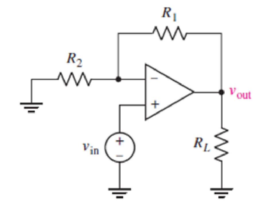
FIGURE 6.40
Expert Solution & Answer
Want to see the full answer?
Check out a sample textbook solution
Students have asked these similar questions
3. Given the measured value of Vp in Fig. 6.69, determine:
(а) Ip.
(b) VDs-
(c) VGG-
14 V
1.6 k2
Vp=9 V
Ipss-8 mA
Vos
V =-4V
1 MA
Figure 6.69
A certain solar cell type has an output
capability of 0.5 Amp at 0.4 V. A series /
parallel solar array has been designed of
such cells with 238 parallel strings and each
string has 221 cells in series.
Current capability of array in Amperes =
A certain solar cell type has an output capability of 0.4 A at 0.6 V. A series / parallel solar array has been designed of such cells with 95 parallel strings and each string has 277 cells in series. Calculate Voltage capability of array.
Chapter 6 Solutions
Loose Leaf for Engineering Circuit Analysis Format: Loose-leaf
Ch. 6.2 - Derive an expression for vout in terms of vin for...Ch. 6.2 - Prob. 2PCh. 6.3 - An historic bridge is showing signs of...Ch. 6.4 - Design a circuit that provides a 12 V output if a...Ch. 6.4 - Design a noninverting Schmitt trigger that that...Ch. 6.5 - Assuming a finite open-loop gain (A), a finite...Ch. 6.5 - Use SPICE to simulate a voltage follower using an...Ch. 6 - For the op amp circuit shown in Fig. 6.39,...Ch. 6 - FIGURE 6.39 Determine the power dissipated by a...Ch. 6 - For the circuit of Fig. 6.40, calculate vout if...
Ch. 6 - For the circuit in Fig. 6.40, find the values of...Ch. 6 - (a) Design a circuit which converts a voltage...Ch. 6 - Prob. 6ECh. 6 - For the circuit of Fig. 6.40, R1 = RL = 50 ....Ch. 6 - Prob. 8ECh. 6 - (a) Design a circuit using only a single op amp...Ch. 6 - Prob. 11ECh. 6 - Determine the output voltage v0 and the current...Ch. 6 - Prob. 13ECh. 6 - Prob. 14ECh. 6 - Prob. 15ECh. 6 - Prob. 16ECh. 6 - Consider the amplifier circuit shown in Fig. 6.46....Ch. 6 - Prob. 18ECh. 6 - Prob. 19ECh. 6 - Prob. 20ECh. 6 - Referring to Fig. 6.49, sketch vout as a function...Ch. 6 - Repeat Exercise 21 using a parameter sweep in...Ch. 6 - Obtain an expression for vout as labeled in the...Ch. 6 - Prob. 24ECh. 6 - Prob. 25ECh. 6 - Prob. 26ECh. 6 - Prob. 27ECh. 6 - Prob. 28ECh. 6 - Prob. 29ECh. 6 - Prob. 30ECh. 6 - Prob. 31ECh. 6 - Determine the value of Vout for the circuit in...Ch. 6 - Calculate V0 for the circuit in Fig. 6.55. FIGURE...Ch. 6 - Prob. 34ECh. 6 - The temperature alarm circuit in Fig. 6.56...Ch. 6 - Prob. 36ECh. 6 - For the circuit depicted in Fig. 6.57, sketch the...Ch. 6 - For the circuit depicted in Fig. 6.58, (a) sketch...Ch. 6 - For the circuit depicted in Fig. 6.59, sketch the...Ch. 6 - In digital logic applications, a +5 V signal...Ch. 6 - Using the temperature sensor in the circuit in...Ch. 6 - Examine the comparator Schmitt trigger circuit in...Ch. 6 - Design the circuit values for the single supply...Ch. 6 - For the instrumentation amplifier shown in Fig....Ch. 6 - A common application for instrumentation...Ch. 6 - (a) Employ the parameters listed in Table 6.3 for...Ch. 6 - Prob. 49ECh. 6 - For the circuit of Fig. 6.62, calculate the...Ch. 6 - Prob. 51ECh. 6 - FIGURE 6.63 (a) For the circuit of Fig. 6.63, if...Ch. 6 - The difference amplifier circuit in Fig. 6.32 has...Ch. 6 - Prob. 55ECh. 6 - Prob. 56ECh. 6 - Prob. 57ECh. 6 - Prob. 58ECh. 6 - Prob. 59ECh. 6 - Prob. 60ECh. 6 - A fountain outside a certain office building is...Ch. 6 - For the circuit of Fig. 6.44, let all resistor...
Knowledge Booster


Learn more about
Need a deep-dive on the concept behind this application? Look no further. Learn more about this topic, electrical-engineering and related others by exploring similar questions and additional content below.Similar questions
- The measuring range of a MC instrument is found to be (0 – 800) mA. This low range instrument is connected with a multiplier resistance of 120 Ω, in order to measure potential difference up to 120V. Determine the resistance of the instrumentarrow_forwardPractice Problem 6. Find the voltage across each of the capacitors in Fig. 6.20. 40 μF 60 µF Answer: U= 45 V, U2 = 45 V, v3 = 15 V, v4 30 V. + 1 - + v3 - 90 V 20 μF 30 V4 Figure 6.20 For Practice Prob. 6.7.arrow_forwardVDD = 1.8 V M1 1 V ミ2k2 6.41. If A = 0, what value of W/L places M1 at the edge of saturation in Fig. 6.53? Figure 6.53arrow_forward
- 6.28 If the transistor in the circuit of Fig. 6.29(a) is replaced with another having half the value of ß (i.e., B=50), find the new value of I, and express the change in I as a percentage. +15 V RB1 100 ΚΩ RB2 50 ΚΩ www www = (a) = Rc 5 ΚΩ RE 3 ΚΩarrow_forward6.51 Determine Leg at terminals a-b of the circuit in Fig. 6.73. 10 mH elll 60 mH 25 mH 20 mH all b ell 30 mH ll Figure 6.73arrow_forward6.51 Determine Leg at terminals a-b of the circuit in Fig. 6.73. 10 mH 60 mH 25 mH rell 20 mH a o -o b ell 30 mH llarrow_forward
- • A certain solar cell type has an output capability of 0.5 A at 0.4Volts. A series / parallel solar array has been designed of such cells with 100 parallel strings and each string has 300 cells in series. Calculate : (i) Voltage capability (ii) Current capability and (iii Power output capability of arrayarrow_forward12. Analyze the circuit of Fig. 6.42 and determine a value for V1, which is refer- enced to ground. 9V 100 Ω www ImA( 1 | FIGURE 6.42 850 Ω Μ Μ 210 ΚΩ ww 850 Ω MoV₁ ΙΜΩ • 250 Ωarrow_forward6.13 Find the voltage across the capacitors in the circuit of Fig. 6.49 under dc conditions. 10 Q 50 Ω 20 Q + 40 Ω C = C2 60 V Figure 6.49arrow_forward
- Q1: Find Lea at the terminals of the circuit in Fig. 6.75. a 6 mH 8 mH 5 mil 12 mH 8 mH 6 mH 4 mH b 10 mH 8 mH Figure 6.75arrow_forward6.51 Detemine Leq at terminals a-b of the circuit in Fig. 6.73. 10 mH all 60 mH 25 mH 20 mH a o 30 mH llarrow_forwardiR R The differentiator in Fig. 6.37 has R = 10 kohm and C = 2 µF. Given that vi = 3t V, determine the output vo. %3Darrow_forward
arrow_back_ios
SEE MORE QUESTIONS
arrow_forward_ios
Recommended textbooks for you
 Introductory Circuit Analysis (13th Edition)Electrical EngineeringISBN:9780133923605Author:Robert L. BoylestadPublisher:PEARSON
 Delmar's Standard Textbook Of ElectricityElectrical EngineeringISBN:9781337900348Author:Stephen L. HermanPublisher:Cengage Learning
 Programmable Logic ControllersElectrical EngineeringISBN:9780073373843Author:Frank D. PetruzellaPublisher:McGraw-Hill Education
 Fundamentals of Electric CircuitsElectrical EngineeringISBN:9780078028229Author:Charles K Alexander, Matthew SadikuPublisher:McGraw-Hill Education
 Electric Circuits. (11th Edition)Electrical EngineeringISBN:9780134746968Author:James W. Nilsson, Susan RiedelPublisher:PEARSON
 Engineering ElectromagneticsElectrical EngineeringISBN:9780078028151Author:Hayt, William H. (william Hart), Jr, BUCK, John A.Publisher:Mcgraw-hill Education,
Introductory Circuit Analysis (13th Edition)
Electrical Engineering
ISBN:9780133923605
Author:Robert L. Boylestad
Publisher:PEARSON
Delmar's Standard Textbook Of Electricity
Electrical Engineering
ISBN:9781337900348
Author:Stephen L. Herman
Publisher:Cengage Learning
Programmable Logic Controllers
Electrical Engineering
ISBN:9780073373843
Author:Frank D. Petruzella
Publisher:McGraw-Hill Education
Fundamentals of Electric Circuits
Electrical Engineering
ISBN:9780078028229
Author:Charles K Alexander, Matthew Sadiku
Publisher:McGraw-Hill Education
Electric Circuits. (11th Edition)
Electrical Engineering
ISBN:9780134746968
Author:James W. Nilsson, Susan Riedel
Publisher:PEARSON
Engineering Electromagnetics
Electrical Engineering
ISBN:9780078028151
Author:Hayt, William H. (william Hart), Jr, BUCK, John A.
Publisher:Mcgraw-hill Education,
Inductors Explained - The basics how inductors work working principle; Author: The Engineering Mindset;https://www.youtube.com/watch?v=KSylo01n5FY;License: Standard Youtube License