
Loose Leaf for Engineering Circuit Analysis Format: Loose-leaf
9th Edition
ISBN: 9781259989452
Author: Hayt
Publisher: Mcgraw Hill Publishers
expand_more
expand_more
format_list_bulleted
Concept explainers
Videos
Textbook Question
Chapter 6, Problem 22E
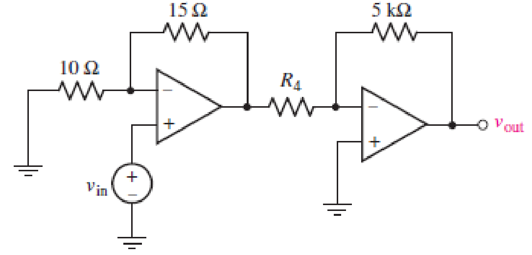
Repeat Exercise 21 using a parameter sweep in SPICE.
Referring to Fig. 6.49, sketch vout as a function of (a) vin over the range of −2 V ≤ vin ≤ +2 V, if R4 = 2 kΩ; (b) R4 over the range of 1 kΩ ≤ R4 ≤ 10 kΩ, if vin = 300 mV.
Expert Solution & Answer
Want to see the full answer?
Check out a sample textbook solution
Students have asked these similar questions
For the circuit below, let Vin = 8 V. You are to select resistor values to guarantee an output voltage with magnitude 4V. Assume that the op amps are ideal.
R₁
FIGURE 6.51
R₂
www
R3
50 ΚΩ
200 ΚΩ
www
out
A certain solar cell type has an output capability of
0.9 A at 0.6 V. A series / parallel solar array has been
designed of such cells with 144 parallel strings and
each string has 210 cells in series. Calculate Current
capability of array.
A certain solar cell type has an output capability of 9.2 A at 0.7 V. A series / parallel solar array has
been designed of such cells with 11 parallel strings and each string has 114 cells in series.
Calculate Voltage capability of array.
Chapter 6 Solutions
Loose Leaf for Engineering Circuit Analysis Format: Loose-leaf
Ch. 6.2 - Derive an expression for vout in terms of vin for...Ch. 6.2 - Prob. 2PCh. 6.3 - An historic bridge is showing signs of...Ch. 6.4 - Design a circuit that provides a 12 V output if a...Ch. 6.4 - Design a noninverting Schmitt trigger that that...Ch. 6.5 - Assuming a finite open-loop gain (A), a finite...Ch. 6.5 - Use SPICE to simulate a voltage follower using an...Ch. 6 - For the op amp circuit shown in Fig. 6.39,...Ch. 6 - FIGURE 6.39 Determine the power dissipated by a...Ch. 6 - For the circuit of Fig. 6.40, calculate vout if...
Ch. 6 - For the circuit in Fig. 6.40, find the values of...Ch. 6 - (a) Design a circuit which converts a voltage...Ch. 6 - Prob. 6ECh. 6 - For the circuit of Fig. 6.40, R1 = RL = 50 ....Ch. 6 - Prob. 8ECh. 6 - (a) Design a circuit using only a single op amp...Ch. 6 - Prob. 11ECh. 6 - Determine the output voltage v0 and the current...Ch. 6 - Prob. 13ECh. 6 - Prob. 14ECh. 6 - Prob. 15ECh. 6 - Prob. 16ECh. 6 - Consider the amplifier circuit shown in Fig. 6.46....Ch. 6 - Prob. 18ECh. 6 - Prob. 19ECh. 6 - Prob. 20ECh. 6 - Referring to Fig. 6.49, sketch vout as a function...Ch. 6 - Repeat Exercise 21 using a parameter sweep in...Ch. 6 - Obtain an expression for vout as labeled in the...Ch. 6 - Prob. 24ECh. 6 - Prob. 25ECh. 6 - Prob. 26ECh. 6 - Prob. 27ECh. 6 - Prob. 28ECh. 6 - Prob. 29ECh. 6 - Prob. 30ECh. 6 - Prob. 31ECh. 6 - Determine the value of Vout for the circuit in...Ch. 6 - Calculate V0 for the circuit in Fig. 6.55. FIGURE...Ch. 6 - Prob. 34ECh. 6 - The temperature alarm circuit in Fig. 6.56...Ch. 6 - Prob. 36ECh. 6 - For the circuit depicted in Fig. 6.57, sketch the...Ch. 6 - For the circuit depicted in Fig. 6.58, (a) sketch...Ch. 6 - For the circuit depicted in Fig. 6.59, sketch the...Ch. 6 - In digital logic applications, a +5 V signal...Ch. 6 - Using the temperature sensor in the circuit in...Ch. 6 - Examine the comparator Schmitt trigger circuit in...Ch. 6 - Design the circuit values for the single supply...Ch. 6 - For the instrumentation amplifier shown in Fig....Ch. 6 - A common application for instrumentation...Ch. 6 - (a) Employ the parameters listed in Table 6.3 for...Ch. 6 - Prob. 49ECh. 6 - For the circuit of Fig. 6.62, calculate the...Ch. 6 - Prob. 51ECh. 6 - FIGURE 6.63 (a) For the circuit of Fig. 6.63, if...Ch. 6 - The difference amplifier circuit in Fig. 6.32 has...Ch. 6 - Prob. 55ECh. 6 - Prob. 56ECh. 6 - Prob. 57ECh. 6 - Prob. 58ECh. 6 - Prob. 59ECh. 6 - Prob. 60ECh. 6 - A fountain outside a certain office building is...Ch. 6 - For the circuit of Fig. 6.44, let all resistor...
Knowledge Booster


Learn more about
Need a deep-dive on the concept behind this application? Look no further. Learn more about this topic, electrical-engineering and related others by exploring similar questions and additional content below.Similar questions
- Design the following conditions using an operational amplifier: Cadmium sulfide (CdS) is commonly used to fabricate resistors whose value depends on the intensity of light shining on its surface. In Figure 1, a CdS “photocell” is used as the feedback resistor Rf. In total darkness, it has a resistance of 100kΩ and a resistance of 10kΩ under a light intensity of 6 candela. RL represents a circuit that is activated when a voltage of 1.5V or less is applied to its terminals. Choose R1 and VS so that the circuit represented by RL is activated by a light of 2 candela or brighter.arrow_forward5. Design an op-amp Voltmeter circuit which can measure a maximum input of 20 mV The op-amp input current is 0.2 µA, and the meter circuit has Im= 100 µA FSD and Rm=10kQ. Determine suitable resistance values for Ra and Rarrow_forwardDesign an Op Amp Circuit which gives Out put Noltage an Vo = 5 V, - 3 V, +7d (5Vi -3V%)arrow_forward
- 6.19 Obtain the equivalent capacitance of the circuit in Fig. 6.54. 35 μF Figure 6.54 40 μF 10 μF 10 μF 20 μF 15 μF 15 μF For Prob. 6.19. b 5 μF HHarrow_forwarda) The waveform in Figure 1(a) is applied to the input of the circuit in Figure 1(b). Analyse, find and plot the output. Vi (v) R =5M iR ww- 4V C=400nF a + 1 2 3 t(s) -4V Figure 1(a) Figure 1(b) b) Design a circuit using a single op amp to generate the following output, vo = - | (4v, + 2v2 + 10vz)dt If the integrating capacitor is C = 1µF, obtain other component values.arrow_forwardExercise The buck dc-dc converter of Fig. 6-3a has the following parameters: V = 50 V D = 0.4 L = 400 µH C = 100 µ.F f= 20 kHz R= 20 N Assuming ideal components, calculate (a) the output voltage V, (b) the maximum and minimum inductor current, and (c) the output voltage ripple.arrow_forward
- The measuring range of a MC instrument is found to be (0 – 800) mA. This low range instrument is connected with a multiplier resistance of 120 Ω, in order to measure potential difference up to 120V. Determine the resistance of the instrumentarrow_forwardFind the voltage across each of the capacitors in Fig. 6.20. 40 pF 60 aF 90 V 20 uF 30 uF Figure 6.20arrow_forwardTo increase the 75 V battery voltage to 100 V, a da-da circuit is required is heard. The converter inductance is 200 μH and the load resistance is 2.2 Ω.Powerswitch has a transmission time of 50 μs and operates in continuous transmission. According to this; d) Find the average value of the input current and the output current. e) Find the minimum and maximum values of the input current. f) Output to be used to limit the fluctuation in the input voltage to 10% of the output voltage.Find the capacity of the circuit.arrow_forward
- Practice Problem 6. Find the voltage across each of the capacitors in Fig. 6.20. 40 μF 60 µF Answer: U= 45 V, U2 = 45 V, v3 = 15 V, v4 30 V. + 1 - + v3 - 90 V 20 μF 30 V4 Figure 6.20 For Practice Prob. 6.7.arrow_forwardThe R-L Circuit: An inductor with an inductance of 2.50 H and a resistance of 7.00 n is connected to the terminals ofa battery with an emf of 6.00 V and an internal resistance of 1.00 n. What is the rate ofincrease of current at the instant when the current is 0.500 A? A) 0.8 A/s B) 0.6 A/s C) 0.4 A/s D) zero E) None of the above.arrow_forwardHow can you improve the overall gain just using a capacitor? Explain where you would connect it and calculate the new gain. (g) VDD VDD = 2V R=4KW R, = 4KW Rp2 R Rp1 M2 Cp2 RDI =4KW Rp2 =4KW R$1=4KW Rs2 = 6KW in CG R$2 R2 Rs1 Csi Vss = 0 V Figure 5arrow_forward
arrow_back_ios
SEE MORE QUESTIONS
arrow_forward_ios
Recommended textbooks for you
 Introductory Circuit Analysis (13th Edition)Electrical EngineeringISBN:9780133923605Author:Robert L. BoylestadPublisher:PEARSON
 Delmar's Standard Textbook Of ElectricityElectrical EngineeringISBN:9781337900348Author:Stephen L. HermanPublisher:Cengage Learning
 Programmable Logic ControllersElectrical EngineeringISBN:9780073373843Author:Frank D. PetruzellaPublisher:McGraw-Hill Education
 Fundamentals of Electric CircuitsElectrical EngineeringISBN:9780078028229Author:Charles K Alexander, Matthew SadikuPublisher:McGraw-Hill Education
 Electric Circuits. (11th Edition)Electrical EngineeringISBN:9780134746968Author:James W. Nilsson, Susan RiedelPublisher:PEARSON
 Engineering ElectromagneticsElectrical EngineeringISBN:9780078028151Author:Hayt, William H. (william Hart), Jr, BUCK, John A.Publisher:Mcgraw-hill Education,
Introductory Circuit Analysis (13th Edition)
Electrical Engineering
ISBN:9780133923605
Author:Robert L. Boylestad
Publisher:PEARSON
Delmar's Standard Textbook Of Electricity
Electrical Engineering
ISBN:9781337900348
Author:Stephen L. Herman
Publisher:Cengage Learning
Programmable Logic Controllers
Electrical Engineering
ISBN:9780073373843
Author:Frank D. Petruzella
Publisher:McGraw-Hill Education
Fundamentals of Electric Circuits
Electrical Engineering
ISBN:9780078028229
Author:Charles K Alexander, Matthew Sadiku
Publisher:McGraw-Hill Education
Electric Circuits. (11th Edition)
Electrical Engineering
ISBN:9780134746968
Author:James W. Nilsson, Susan Riedel
Publisher:PEARSON
Engineering Electromagnetics
Electrical Engineering
ISBN:9780078028151
Author:Hayt, William H. (william Hart), Jr, BUCK, John A.
Publisher:Mcgraw-hill Education,
Current Divider Rule; Author: Neso Academy;https://www.youtube.com/watch?v=hRU1mKWUehY;License: Standard YouTube License, CC-BY