
Loose Leaf for Engineering Circuit Analysis Format: Loose-leaf
9th Edition
ISBN: 9781259989452
Author: Hayt
Publisher: Mcgraw Hill Publishers
expand_more
expand_more
format_list_bulleted
Concept explainers
Videos
Textbook Question
Chapter 6, Problem 17E
Consider the amplifier circuit shown in Fig. 6.46. What value of Rf will yield vout = 2 V when Is = −5/3 mA and RY = 2RX = 500 Ω?
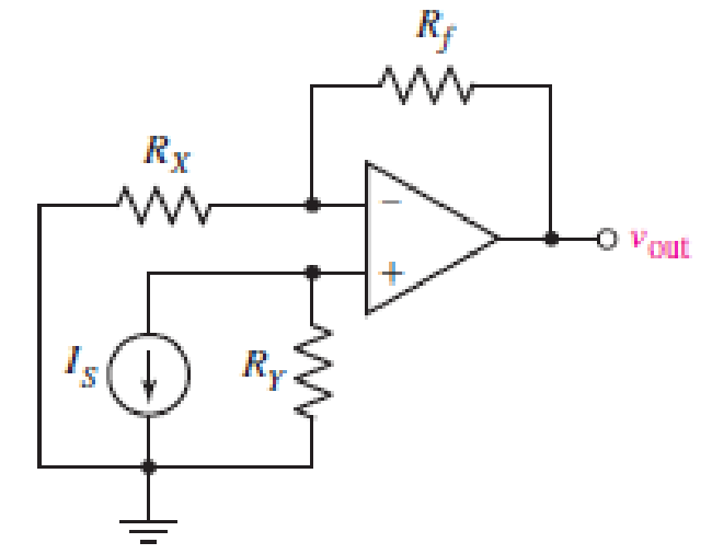
FIGURE 6.46
Expert Solution & Answer
Want to see the full answer?
Check out a sample textbook solution
Students have asked these similar questions
HW6.5. BJT DC Analysis
+
VCE
V1
5 V
Assume: VBE(on) = .7V, VCEsat = .2V, B = 40
Find the values of Ic and V
Ic=
out as marked.
number (rtol=0.01, atol=1e-05)
R1
4 ΚΩ
number (rtol=0.01, atol=1e-05)
R2
4 ΚΩ
mA
V
?
R3
100 ΚΩ
Vout
Q5-
Perform the large signal analysis for the following circuit. 4.51
if IS = 6 x 10-16 A.
1.5
+9₁
X
1kQ2
Vcc=2 V
An op amp has Vsat = +/- 13 V, SR = 1.7 V/μs, and is used as a comparator. What is the approximate time it takes to transition from one output state to the other?
Chapter 6 Solutions
Loose Leaf for Engineering Circuit Analysis Format: Loose-leaf
Ch. 6.2 - Derive an expression for vout in terms of vin for...Ch. 6.2 - Prob. 2PCh. 6.3 - An historic bridge is showing signs of...Ch. 6.4 - Design a circuit that provides a 12 V output if a...Ch. 6.4 - Design a noninverting Schmitt trigger that that...Ch. 6.5 - Assuming a finite open-loop gain (A), a finite...Ch. 6.5 - Use SPICE to simulate a voltage follower using an...Ch. 6 - For the op amp circuit shown in Fig. 6.39,...Ch. 6 - FIGURE 6.39 Determine the power dissipated by a...Ch. 6 - For the circuit of Fig. 6.40, calculate vout if...
Ch. 6 - For the circuit in Fig. 6.40, find the values of...Ch. 6 - (a) Design a circuit which converts a voltage...Ch. 6 - Prob. 6ECh. 6 - For the circuit of Fig. 6.40, R1 = RL = 50 ....Ch. 6 - Prob. 8ECh. 6 - (a) Design a circuit using only a single op amp...Ch. 6 - Prob. 11ECh. 6 - Determine the output voltage v0 and the current...Ch. 6 - Prob. 13ECh. 6 - Prob. 14ECh. 6 - Prob. 15ECh. 6 - Prob. 16ECh. 6 - Consider the amplifier circuit shown in Fig. 6.46....Ch. 6 - Prob. 18ECh. 6 - Prob. 19ECh. 6 - Prob. 20ECh. 6 - Referring to Fig. 6.49, sketch vout as a function...Ch. 6 - Repeat Exercise 21 using a parameter sweep in...Ch. 6 - Obtain an expression for vout as labeled in the...Ch. 6 - Prob. 24ECh. 6 - Prob. 25ECh. 6 - Prob. 26ECh. 6 - Prob. 27ECh. 6 - Prob. 28ECh. 6 - Prob. 29ECh. 6 - Prob. 30ECh. 6 - Prob. 31ECh. 6 - Determine the value of Vout for the circuit in...Ch. 6 - Calculate V0 for the circuit in Fig. 6.55. FIGURE...Ch. 6 - Prob. 34ECh. 6 - The temperature alarm circuit in Fig. 6.56...Ch. 6 - Prob. 36ECh. 6 - For the circuit depicted in Fig. 6.57, sketch the...Ch. 6 - For the circuit depicted in Fig. 6.58, (a) sketch...Ch. 6 - For the circuit depicted in Fig. 6.59, sketch the...Ch. 6 - In digital logic applications, a +5 V signal...Ch. 6 - Using the temperature sensor in the circuit in...Ch. 6 - Examine the comparator Schmitt trigger circuit in...Ch. 6 - Design the circuit values for the single supply...Ch. 6 - For the instrumentation amplifier shown in Fig....Ch. 6 - A common application for instrumentation...Ch. 6 - (a) Employ the parameters listed in Table 6.3 for...Ch. 6 - Prob. 49ECh. 6 - For the circuit of Fig. 6.62, calculate the...Ch. 6 - Prob. 51ECh. 6 - FIGURE 6.63 (a) For the circuit of Fig. 6.63, if...Ch. 6 - The difference amplifier circuit in Fig. 6.32 has...Ch. 6 - Prob. 55ECh. 6 - Prob. 56ECh. 6 - Prob. 57ECh. 6 - Prob. 58ECh. 6 - Prob. 59ECh. 6 - Prob. 60ECh. 6 - A fountain outside a certain office building is...Ch. 6 - For the circuit of Fig. 6.44, let all resistor...
Knowledge Booster


Learn more about
Need a deep-dive on the concept behind this application? Look no further. Learn more about this topic, electrical-engineering and related others by exploring similar questions and additional content below.Similar questions
- Q6 Design a linear oscillator, using a Hartley configuration, to generate oscillating signal at frequency f = 15 kHz by choosing an appropriate value of L1 and L2, knowing that the inductance is C = 200 µF, the transconductance when the transistor is biased in operation is gm = 2.5 mS and the gate resistance RG = 5 kN. (a) Draw the electric circuit and explain the role of each component. (b) Derive the small signal equivalent model of the open loop circuit and state your main assumptions. Derive the oscillation condition. State any assumptions you make and show all steps of your calculation (c) (d) The main hypothesis for the design of the oscillator in the previous question is that the resonance frequency falls in the mid-band frequency range of the amplifier. Explain briefly what happen and how you would proceed in the case that you want to design an oscillator with resonance frequency in the high frequency regime.arrow_forwardQ6 Design a linear oscillator, using a Hartley configuration, to generate oscillating signal at frequency f = 15 kHz by choosing an appropriate value of Lj and L2, knowing that the inductance is C = 200 µF, the transconductance when the transistor is biased in operation is gm = 2.5 mS and the gate resistance Rg = 5 kN. (a) Draw the electric circuit and explain the role of each component. (b) Derive the small signal equivalent model of the open loop circuit and state your main assumptions. Derive the oscillation condition. State any assumptions you make and show all steps of your calculation (c) (d) The main hypothesis for the design of the oscillator in the previous question is that the resonance frequency falls in the mid-band frequency range of the amplifier. Explain briefly what happen and how you would proceed in the case that you want to design an oscillator with resonance frequency in the high frequency regime.arrow_forwardFor the signal and circuit of Figure 6, the op-amp has a slew rate of SR=0.75 V/µs. a) Calculate the maximum frequency that may be used. b) Determine if the signal will be an amplified duplicate at the output.arrow_forward
- In the small-signal equivalent circuit, the DC voltage source is replaced by a open circuit. Select one O True O False The two types of free charge carriers are electrons and holes Select onearrow_forwardFor the inverting amplifier in Fig. 6_3, if Vin=-50 cos10t (V), R₁= 200 Ohm and R-20 Ohm; what is Vout ? Vin 5 cos10t (V) - 5 cos10t (V) R1 ww Fig. 6_3 -1000 cos10t (V) O 1000 cos10t (V) Rf ww Voutarrow_forwardFor the circuit below, let Vin = 8 V. You are to select resistor values to guarantee an output voltage with magnitude 4V. Assume that the op amps are ideal. R₁ FIGURE 6.51 R₂ www R3 50 ΚΩ 200 ΚΩ www outarrow_forward
- Q6.) Identify whether the following statement are true(T) or false (F) 4- A piezo-electrical transducer is an example for active transducer. 5- The (1) is remove form control register in successive approximation DVM when (Vin) is greater than VD (A/D convertor voltage).arrow_forwardne Practice (4.7): Design a difference amplifier with gain 7.5.arrow_forwardA silicon photodiode is connected to an op-amp as indicated. Under an illuminance of 500 lux, the photocurrent Ip is 80 nA. I R = 1MQ w out Write down the values of 11, 12 and Ip. From these values, deduce the output voltage. Briefly describe how this circuit works. c) Will this circuit work under sunlight? The illuminance of sunlight is about 100,000 lux. You may assume the photocurrent respond linearly with incident light flux, and the op-amp is powered between 9V alkaline cell. (i.e., V+ = 9V, V¯ at ground).arrow_forward
- Design an inverting op amp circuit with 6.5 gainarrow_forwardQ9 (Hor. 4.6) + o VIN 2 RI VOUT Draw the VIN-VOUT transfer characteristic. D, has properties: Ⓒ Vf = 0.7 (forward voltage drop) Ⓒ V₂+ = 5V ZT (3) √z ≈ 052arrow_forwardDesign a VCO circuit that will produce a square wave output at 2.6 kHz.arrow_forward
arrow_back_ios
SEE MORE QUESTIONS
arrow_forward_ios
Recommended textbooks for you
 Introductory Circuit Analysis (13th Edition)Electrical EngineeringISBN:9780133923605Author:Robert L. BoylestadPublisher:PEARSON
 Delmar's Standard Textbook Of ElectricityElectrical EngineeringISBN:9781337900348Author:Stephen L. HermanPublisher:Cengage Learning
 Programmable Logic ControllersElectrical EngineeringISBN:9780073373843Author:Frank D. PetruzellaPublisher:McGraw-Hill Education
 Fundamentals of Electric CircuitsElectrical EngineeringISBN:9780078028229Author:Charles K Alexander, Matthew SadikuPublisher:McGraw-Hill Education
 Electric Circuits. (11th Edition)Electrical EngineeringISBN:9780134746968Author:James W. Nilsson, Susan RiedelPublisher:PEARSON
 Engineering ElectromagneticsElectrical EngineeringISBN:9780078028151Author:Hayt, William H. (william Hart), Jr, BUCK, John A.Publisher:Mcgraw-hill Education,
Introductory Circuit Analysis (13th Edition)
Electrical Engineering
ISBN:9780133923605
Author:Robert L. Boylestad
Publisher:PEARSON
Delmar's Standard Textbook Of Electricity
Electrical Engineering
ISBN:9781337900348
Author:Stephen L. Herman
Publisher:Cengage Learning
Programmable Logic Controllers
Electrical Engineering
ISBN:9780073373843
Author:Frank D. Petruzella
Publisher:McGraw-Hill Education
Fundamentals of Electric Circuits
Electrical Engineering
ISBN:9780078028229
Author:Charles K Alexander, Matthew Sadiku
Publisher:McGraw-Hill Education
Electric Circuits. (11th Edition)
Electrical Engineering
ISBN:9780134746968
Author:James W. Nilsson, Susan Riedel
Publisher:PEARSON
Engineering Electromagnetics
Electrical Engineering
ISBN:9780078028151
Author:Hayt, William H. (william Hart), Jr, BUCK, John A.
Publisher:Mcgraw-hill Education,
Current Divider Rule; Author: Neso Academy;https://www.youtube.com/watch?v=hRU1mKWUehY;License: Standard YouTube License, CC-BY