
Applied Statics and Strength of Materials (6th Edition)
6th Edition
ISBN: 9780133840544
Author: George F. Limbrunner, Craig D'Allaird, Leonard Spiegel
Publisher: PEARSON
expand_more
expand_more
format_list_bulleted
Concept explainers
Videos
Textbook Question
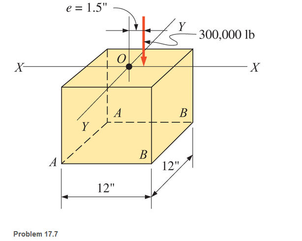
Chapter 17, Problem 17.7P
A short compression member is subjected to a compressive load of 300,000 lb at an eccentricity of 1.5 in., as shown. The member is 12 in. by 12 in. in cross section. Calculate the combined stresses at the outer edges AA and BB.
Expert Solution & Answer

Trending nowThis is a popular solution!

Students have asked these similar questions
A circular rod of diameter d and length 3d is
subjected to a compressive force F acting at the
top point as shown below. Calculate the stress at
the bottom most support point A
3d -
d
A
An iron column of annular cross-section has an outer diameter of 200 mm and is subjected to a force of 75 kN. Find the thickness of the wall if the allowable compressive stress is 10 Mpa.
A solid steel bar with a diameter of 50 mm is subjected to three forces as shown in the figure, determine the main stresses in point B.
Chapter 17 Solutions
Applied Statics and Strength of Materials (6th Edition)
Ch. 17 - Prob. 17.1PCh. 17 - A horizontal 30-ft simple span beam is supported...Ch. 17 - A 1-in.-by-4-in, steel bar is subjected to the...Ch. 17 - A W410100 structural steel wide-flange section is...Ch. 17 - A W1272 structural steel wide-flange section is...Ch. 17 - A solid steel shaft 3 in. in diameter and 4 ft...Ch. 17 - A short compression member is subjected to a...Ch. 17 - With reference to Problem 17.7, calculate the...Ch. 17 - A section of a 51-mm-diameter standard-weight...Ch. 17 - For the pipe of Problem 17.9, compute the maximum...
Ch. 17 - A concrete pedestal is in the shape of a cube and...Ch. 17 - 17.12 For the pedestal of Problem 17.11, assume...Ch. 17 - 17.13 Rework Problem 17.11, but assume that the...Ch. 17 - A 12-in-square concrete pedestal is subjected to a...Ch. 17 - 17.15 A short compression member is subjected to a...Ch. 17 - A rectangular concrete footing, 4 ft by 8 ft in...Ch. 17 - The bending and shear stresses developed at a...Ch. 17 - Stresses developed at a point in a machine part...Ch. 17 - Calculate the principal stresses at points A and B...Ch. 17 - 17.20 Rework Problem 17.19 using P = 8000 lb and...Ch. 17 - 17.21 A 1-in.-square steel bar is subjected to an...Ch. 17 - 17.22 A bar having a cross-sectional area of 6...Ch. 17 - Rework Problem 17.22, changing the load to a...Ch. 17 - Solve Problem l7.17 using Mohr’s circle.Ch. 17 - For the elements shown in Problem 17.18, use...Ch. 17 - Solve Problem 17.19 using Mohr’s circle.Ch. 17 - In Problem 17.19, change the load to 8000 lb and...Ch. 17 - For the following computer problems, any...Ch. 17 - For the following computer problems, any...Ch. 17 - For the following computer problems, any...Ch. 17 - For the following computer problems, any...Ch. 17 - A 4-in.-by-8-in. (S4S) Douglas fir timber beam is...Ch. 17 - A horizontal flexural member (a girt) in the wall...Ch. 17 - A simply supported W1850 structural steel...Ch. 17 - A steel link in a machine is designed to avoid...Ch. 17 - 17.36 An 8-in-square (S4S) vertical timber post is...Ch. 17 - A short 3-in.-square steel bar with a...Ch. 17 - A timber member 150 mm by 250 mm (S4S) is loaded...Ch. 17 - A concrete wall 8 ft high and 3 ft thick is...Ch. 17 - 17.40 A short compression member is subjected to a...Ch. 17 - 17.41 Calculate the maximum eccentric load that...Ch. 17 - A short compression member is subjected to two...Ch. 17 - 17.43 Calculate the force P that may be applied to...Ch. 17 - 17.44 A load of 1000 lb is supported on a...Ch. 17 - 17.45 A short compression member is subjected to...Ch. 17 - 17.46 A structural steel wide-flange section is...Ch. 17 - 17.47 A cast-iron frame for a piece of industrial...Ch. 17 - 17.48 The assembly shown is used in a machine. It...Ch. 17 - 17.49 A 50-mm-diameter solid steel shaft is...Ch. 17 - An element of a machine member is subjected to the...Ch. 17 - 17.51 A short-span cantilever built-up beam has...Ch. 17 - Solve Problem 17.50 using Mohr’s circle.Ch. 17 - 17.53 A cantilever beam is subjected to an...Ch. 17 - A 6-in.-diameter solid shaft is subjected to a...Ch. 17 - Rework parts (b) and (c) of Example 17.7 using...
Knowledge Booster


Learn more about
Need a deep-dive on the concept behind this application? Look no further. Learn more about this topic, mechanical-engineering and related others by exploring similar questions and additional content below.Similar questions
- I The cross-sectional area of each member of the truss is 1200 mm". Calculate the stresses in members CD and BC. State whether the stresses (in MPa) are tensile or compressive. 300 kN 300 kN 6m 4 m 4 m C 3m E 3m 100 kN 200 KNarrow_forwardCalculate the principal stresses at point A for the loading case.arrow_forwardA compression load of P = 50 kips is applied to a 2 in. by 2 in. square post, as shown. Determine the normal stress o, perpendicular to plane AB and the shear stress Ty parallel to plane AB. Assume a = 30°. P A B Calculate the normal force N perpendicular to the plane AB and the shear force V parallel to plane AB. Report both answers as positive numbers. Answers: N = i kips, V= i kips.arrow_forward
- Calculate the normal stresses at points A and B of the bracket caused by the 30-kN force.arrow_forwardThe figure shows the cross section of a circular steel tube that is filled with concrete and topped with a rigid cap. Calculate the stresses in the steel and in the concrete caused by the 200-kip axial load. Use Est = 29 × 106 psi and Eco = 3:5 × 10⁶ psi.arrow_forward5 Figure 5 shows a thick cylinder of 50 mm internal radius and 115 mm outer radius is subjected to an internal pressure of 60 MN/m² and an extemal pressure of 30 MN/m?. Determine the hoop and radial stresses at the inside and outside of the cylinder together with the longitudinal stress if the cylinder is assumed to have closed ends using analytical and graphical approaches.arrow_forward
- A circular tube AB is fixed at one end and free at the other end. The tubeis subjected to axialforce at joint B. If the outer diameter of the tube is 3 in, and thethickness is 3/4 in., calculate the maximum normal stress in the tubearrow_forwardCalculate non-zero stress components (normal and shear) at points A, B and C. Point C is located at the center of the cross section attached to the wall. Calculate non-zero strain components at point B. Neglect shear stress due to shear force. Given: loading F = 400 N, P-2000 N, and T = 75 N·m, Young's modulus E = 70 GPa, Poisson's ratio v = 0.25 15-mm D. -100 mmarrow_forwardFor the structure shown in the figure, calculate the size of the bolt and area of the bear- 1-18. ing plates required if the allowable stresses are 18,000 psi in tension and 500 psi in bearing. Neglect the weight of the beams. Ans. 1.25 in., 30 in.2 Bearing plates 6" x 10 " One bolt 9 k 6" x 10" 3' 6' 3' 6'arrow_forward
- A machine having a mass of 9555 kg is supported by three solid steel rods arranged as showed in the following figure. Each rod has a diameter of 50 mm. Compute the stresses in MPa in the three rods of AB, BC, and BD Rods 70 45 Machinearrow_forwardProblem 3. Compute the maximum tensile stress in the bracket (rectangular cross section) 80 mm 20 mm thick 40° 4.2 kN -400 mm-arrow_forwardThe cross section of the CD part of the crane boom in the picture is a standard 50x150mm2. Determine the normal stress at the center of the part. Use exact values in the calculation, just round the answers! The mass of the load is: mk=59033 kgarrow_forward
arrow_back_ios
SEE MORE QUESTIONS
arrow_forward_ios
Recommended textbooks for you
 Elements Of ElectromagneticsMechanical EngineeringISBN:9780190698614Author:Sadiku, Matthew N. O.Publisher:Oxford University Press
 Mechanics of Materials (10th Edition)Mechanical EngineeringISBN:9780134319650Author:Russell C. HibbelerPublisher:PEARSON
 Thermodynamics: An Engineering ApproachMechanical EngineeringISBN:9781259822674Author:Yunus A. Cengel Dr., Michael A. BolesPublisher:McGraw-Hill Education
 Control Systems EngineeringMechanical EngineeringISBN:9781118170519Author:Norman S. NisePublisher:WILEY
 Mechanics of Materials (MindTap Course List)Mechanical EngineeringISBN:9781337093347Author:Barry J. Goodno, James M. GerePublisher:Cengage Learning
 Engineering Mechanics: StaticsMechanical EngineeringISBN:9781118807330Author:James L. Meriam, L. G. Kraige, J. N. BoltonPublisher:WILEY
Elements Of Electromagnetics
Mechanical Engineering
ISBN:9780190698614
Author:Sadiku, Matthew N. O.
Publisher:Oxford University Press
Mechanics of Materials (10th Edition)
Mechanical Engineering
ISBN:9780134319650
Author:Russell C. Hibbeler
Publisher:PEARSON
Thermodynamics: An Engineering Approach
Mechanical Engineering
ISBN:9781259822674
Author:Yunus A. Cengel Dr., Michael A. Boles
Publisher:McGraw-Hill Education
Control Systems Engineering
Mechanical Engineering
ISBN:9781118170519
Author:Norman S. Nise
Publisher:WILEY
Mechanics of Materials (MindTap Course List)
Mechanical Engineering
ISBN:9781337093347
Author:Barry J. Goodno, James M. Gere
Publisher:Cengage Learning
Engineering Mechanics: Statics
Mechanical Engineering
ISBN:9781118807330
Author:James L. Meriam, L. G. Kraige, J. N. Bolton
Publisher:WILEY
Everything About COMBINED LOADING in 10 Minutes! Mechanics of Materials; Author: Less Boring Lectures;https://www.youtube.com/watch?v=N-PlI900hSg;License: Standard youtube license