
Applied Statics and Strength of Materials (6th Edition)
6th Edition
ISBN: 9780133840544
Author: George F. Limbrunner, Craig D'Allaird, Leonard Spiegel
Publisher: PEARSON
expand_more
expand_more
format_list_bulleted
Videos
Textbook Question
Chapter 17, Problem 17.2P
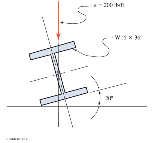
A horizontal 30-ft simple span beam is supported on a 20° slope and is loaded as shown. The uniformly distributed line load covers the full span. Determine the maximum tensile and compressive stresses due to bending. The beam weight is included in the given load.
Expert Solution & Answer
Want to see the full answer?
Check out a sample textbook solution
Students have asked these similar questions
A 2500 lbs point load is placed at 4 inches from support A. The beam is simply supported with a span of 16 inches. Determine the maximum flexural stress of the beam.
A 200 mm square hollow section at 15 mm thick, is used as simply supported beam both ends. The simple beam carries 10 kN/m uniformly distributed load applied on its entire span. Determine the maximum flexural stress (kPa) caused by the uniform load.
beam carries a concentrated load (10 KN) and a total uniformly distributed load of (5 KN/m) as shown in Fig .Determine the maximum tensile and compressive bending stresses developed in the beam if the T- section is inverted.
Chapter 17 Solutions
Applied Statics and Strength of Materials (6th Edition)
Ch. 17 - Prob. 17.1PCh. 17 - A horizontal 30-ft simple span beam is supported...Ch. 17 - A 1-in.-by-4-in, steel bar is subjected to the...Ch. 17 - A W410100 structural steel wide-flange section is...Ch. 17 - A W1272 structural steel wide-flange section is...Ch. 17 - A solid steel shaft 3 in. in diameter and 4 ft...Ch. 17 - A short compression member is subjected to a...Ch. 17 - With reference to Problem 17.7, calculate the...Ch. 17 - A section of a 51-mm-diameter standard-weight...Ch. 17 - For the pipe of Problem 17.9, compute the maximum...
Ch. 17 - A concrete pedestal is in the shape of a cube and...Ch. 17 - 17.12 For the pedestal of Problem 17.11, assume...Ch. 17 - 17.13 Rework Problem 17.11, but assume that the...Ch. 17 - A 12-in-square concrete pedestal is subjected to a...Ch. 17 - 17.15 A short compression member is subjected to a...Ch. 17 - A rectangular concrete footing, 4 ft by 8 ft in...Ch. 17 - The bending and shear stresses developed at a...Ch. 17 - Stresses developed at a point in a machine part...Ch. 17 - Calculate the principal stresses at points A and B...Ch. 17 - 17.20 Rework Problem 17.19 using P = 8000 lb and...Ch. 17 - 17.21 A 1-in.-square steel bar is subjected to an...Ch. 17 - 17.22 A bar having a cross-sectional area of 6...Ch. 17 - Rework Problem 17.22, changing the load to a...Ch. 17 - Solve Problem l7.17 using Mohr’s circle.Ch. 17 - For the elements shown in Problem 17.18, use...Ch. 17 - Solve Problem 17.19 using Mohr’s circle.Ch. 17 - In Problem 17.19, change the load to 8000 lb and...Ch. 17 - For the following computer problems, any...Ch. 17 - For the following computer problems, any...Ch. 17 - For the following computer problems, any...Ch. 17 - For the following computer problems, any...Ch. 17 - A 4-in.-by-8-in. (S4S) Douglas fir timber beam is...Ch. 17 - A horizontal flexural member (a girt) in the wall...Ch. 17 - A simply supported W1850 structural steel...Ch. 17 - A steel link in a machine is designed to avoid...Ch. 17 - 17.36 An 8-in-square (S4S) vertical timber post is...Ch. 17 - A short 3-in.-square steel bar with a...Ch. 17 - A timber member 150 mm by 250 mm (S4S) is loaded...Ch. 17 - A concrete wall 8 ft high and 3 ft thick is...Ch. 17 - 17.40 A short compression member is subjected to a...Ch. 17 - 17.41 Calculate the maximum eccentric load that...Ch. 17 - A short compression member is subjected to two...Ch. 17 - 17.43 Calculate the force P that may be applied to...Ch. 17 - 17.44 A load of 1000 lb is supported on a...Ch. 17 - 17.45 A short compression member is subjected to...Ch. 17 - 17.46 A structural steel wide-flange section is...Ch. 17 - 17.47 A cast-iron frame for a piece of industrial...Ch. 17 - 17.48 The assembly shown is used in a machine. It...Ch. 17 - 17.49 A 50-mm-diameter solid steel shaft is...Ch. 17 - An element of a machine member is subjected to the...Ch. 17 - 17.51 A short-span cantilever built-up beam has...Ch. 17 - Solve Problem 17.50 using Mohr’s circle.Ch. 17 - 17.53 A cantilever beam is subjected to an...Ch. 17 - A 6-in.-diameter solid shaft is subjected to a...Ch. 17 - Rework parts (b) and (c) of Example 17.7 using...
Knowledge Booster


Learn more about
Need a deep-dive on the concept behind this application? Look no further. Learn more about this topic, mechanical-engineering and related others by exploring similar questions and additional content below.Similar questions
- QUESTION 3 If the allowable bending stresses for a beam in one application is 6 kip/in2 in tension. The cross-section of the beam is W8 x 40. If the beam is 10 foot long and simply supported and has a concentrated load applied at x = 3 ft as shown below. • Generate the shear force and bending moment diagram in terms of P; • Based on the allowable maximum bending moment you just obtained above, calculate/ input the mazimm allowable value of the load P: please, pay attention to units, and calculate your answer to 1 decimal place.. 3 ft 7 ft kip.arrow_forwardQuestion 5 Calculate the maximum longitudinal direct stress, plot the stress distribution diagram and determine the location of the neutral axis for a 20 long simply supported beam with a rectangularcross-section that is 160 mm wide and 210 mm deep, which carries a uniformly distributed load of 260 N/m, on its upper surface and a compressive axial load of 220 kN at its free ends. Present schematics showing the distribution of bending direct longitudinal stress, direct load stress, the combined longitudinal direct stress, and identify the neutral axis as well as centroidal axis on the schematic. Show the values of these stresses at the top and bottom surfaces of the cross-section.arrow_forwardFind the maximum stress in the beam if it is fixed at the left end,free at the right end subjected to a uniform distributed load of200 lb/in.arrow_forward
- Determine the maximum tensile and compressive bending stresses in the beam shown. Show: A. Complete process B. free body diagram C. Shear diagram D. Bending moment diagramarrow_forwardDraw the shear-force and bending-moment diagram for the beam shown. Assume the upward reaction provided by the ground to be uniformly distributed. Let a = 5.0 ft, b = 3.4 ft, P = 25 kips, and w = 1.1 kips/ft. Label all significant points on each diagram. Determine the maximum value of (a) the internal shear force and (b) the internal bending moment.Note that answers may be positive or negative. Here, "maximum" refers to the largest magnitude value, but you should enter your shear force and bending moment with the correct sign, using the sign convention presented in Section 7.2 of the textbook. If the magnitudes of the largest positive and largest negative values are the same, enter a positive number.arrow_forwardA timber beam of rectangular section carries a load of 2 kN at mid-span. The beam is simply supported over a span of 3.6 m. If the depth of section is to be twice the breadth, and the bending stress is not to exceed 9 N/mm2 , determine the cross-sectional dimensions.arrow_forward
- A 20 ft long simply supported beam has 15-inch outside diameter with 1-inch-thick circular section. The beam carries 10 lb/ft uniformly distributed load from the right support to its middle span. Another 15 lb concentrated load applied downward in the left-end support. Determine the maximum bending stress (k-lb/ft2) of the simply supported beam.arrow_forward10c The 9.75 m long beam is simply supported at A and B shown below with a uniformly distributed load (UDL) between A and C of 4.75 kN/m and a concentrated point load of 12.50 kN at point D (i.e., midpoint between C & B). Determine the shear force in kilonewtons (kN) at the midpoint of AB (i.e., mid-beam). Assume the beam is weightless and give your answer in kilonewtons (kN) to 2 decimal places. 12.50 kN 4.75 kN/m 1.125 m A 7.50 m 2.25 m в Answer:arrow_forwardAnalyze the beam for stresses at point A and B due to combined effect of loading. Force F is equal to 5000 lbs and P is equal to 3500 lbs.arrow_forward
- A |100 lb B +2+ 4 ft - 180 lb с - 3 -arrow_forwardthe right -angled frame in a uniformly distributed loading equivalent to 200 N for each horizontal projected meter of the frame; tha is, the total load is 1000 N. compute the maximum flexural stress at section a-a if the cross section is a 50 mm square.arrow_forward20 kN 30 (kN/m) B A D 1 m 1 m 2 m Continuous beam with internal hinge at B. All members have constant El. Roller support at D and fixed support at A. Determine the slope at the support D. Use the unit load method i.e., the virtual work I. principle. Consider internal strain energy only due to bending Without doing any calculation, draw the qualitative shapes of axial force, shear force and bending moment diagram for the continuous beam I.arrow_forward
arrow_back_ios
SEE MORE QUESTIONS
arrow_forward_ios
Recommended textbooks for you
 Elements Of ElectromagneticsMechanical EngineeringISBN:9780190698614Author:Sadiku, Matthew N. O.Publisher:Oxford University Press
 Mechanics of Materials (10th Edition)Mechanical EngineeringISBN:9780134319650Author:Russell C. HibbelerPublisher:PEARSON
 Thermodynamics: An Engineering ApproachMechanical EngineeringISBN:9781259822674Author:Yunus A. Cengel Dr., Michael A. BolesPublisher:McGraw-Hill Education
 Control Systems EngineeringMechanical EngineeringISBN:9781118170519Author:Norman S. NisePublisher:WILEY
 Mechanics of Materials (MindTap Course List)Mechanical EngineeringISBN:9781337093347Author:Barry J. Goodno, James M. GerePublisher:Cengage Learning
 Engineering Mechanics: StaticsMechanical EngineeringISBN:9781118807330Author:James L. Meriam, L. G. Kraige, J. N. BoltonPublisher:WILEY
Elements Of Electromagnetics
Mechanical Engineering
ISBN:9780190698614
Author:Sadiku, Matthew N. O.
Publisher:Oxford University Press
Mechanics of Materials (10th Edition)
Mechanical Engineering
ISBN:9780134319650
Author:Russell C. Hibbeler
Publisher:PEARSON
Thermodynamics: An Engineering Approach
Mechanical Engineering
ISBN:9781259822674
Author:Yunus A. Cengel Dr., Michael A. Boles
Publisher:McGraw-Hill Education
Control Systems Engineering
Mechanical Engineering
ISBN:9781118170519
Author:Norman S. Nise
Publisher:WILEY
Mechanics of Materials (MindTap Course List)
Mechanical Engineering
ISBN:9781337093347
Author:Barry J. Goodno, James M. Gere
Publisher:Cengage Learning
Engineering Mechanics: Statics
Mechanical Engineering
ISBN:9781118807330
Author:James L. Meriam, L. G. Kraige, J. N. Bolton
Publisher:WILEY
Mechanics of Materials Lecture: Beam Design; Author: UWMC Engineering;https://www.youtube.com/watch?v=-wVs5pvQPm4;License: Standard Youtube License