
Applied Statics and Strength of Materials (6th Edition)
6th Edition
ISBN: 9780133840544
Author: George F. Limbrunner, Craig D'Allaird, Leonard Spiegel
Publisher: PEARSON
expand_more
expand_more
format_list_bulleted
Videos
Textbook Question
Chapter 17, Problem 17.39SP
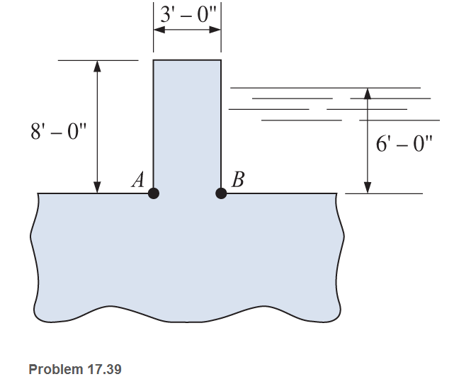
A concrete wall 8 ft high and 3 ft thick is monolithic with a concrete base. The wall has water behind one face to a height of 6 ft, as shown. Calculate the combined normal stresses at points A and B at the bottom of the wall in pounds per square inch and pounds per square foot. Consider a 1-ft length of wall. Assume the unit weight of concrete to be 150 pcf and the unit weight of water to be 62.4 pcf.
Expert Solution & Answer
Want to see the full answer?
Check out a sample textbook solution
Students have asked these similar questions
The wall thickness of the spherical tank is 8mm, calculate the diameter if the allowable stress is 140 MPa and the internal pressure is 60MPa.
The wall thickness of a 900mm diameter spherical tank is 22 mm thick. If the stress is limited to 350 MPa, the allowable internal pressure
The wall thickness of a 1.2 m diameter spherical tank is 1.6875 mm. Calculate the allowable internal pressure if the stress is limited to 55 MPa.
If i will get the same answer again I will report and downvote.
Chapter 17 Solutions
Applied Statics and Strength of Materials (6th Edition)
Ch. 17 - Prob. 17.1PCh. 17 - A horizontal 30-ft simple span beam is supported...Ch. 17 - A 1-in.-by-4-in, steel bar is subjected to the...Ch. 17 - A W410100 structural steel wide-flange section is...Ch. 17 - A W1272 structural steel wide-flange section is...Ch. 17 - A solid steel shaft 3 in. in diameter and 4 ft...Ch. 17 - A short compression member is subjected to a...Ch. 17 - With reference to Problem 17.7, calculate the...Ch. 17 - A section of a 51-mm-diameter standard-weight...Ch. 17 - For the pipe of Problem 17.9, compute the maximum...
Ch. 17 - A concrete pedestal is in the shape of a cube and...Ch. 17 - 17.12 For the pedestal of Problem 17.11, assume...Ch. 17 - 17.13 Rework Problem 17.11, but assume that the...Ch. 17 - A 12-in-square concrete pedestal is subjected to a...Ch. 17 - 17.15 A short compression member is subjected to a...Ch. 17 - A rectangular concrete footing, 4 ft by 8 ft in...Ch. 17 - The bending and shear stresses developed at a...Ch. 17 - Stresses developed at a point in a machine part...Ch. 17 - Calculate the principal stresses at points A and B...Ch. 17 - 17.20 Rework Problem 17.19 using P = 8000 lb and...Ch. 17 - 17.21 A 1-in.-square steel bar is subjected to an...Ch. 17 - 17.22 A bar having a cross-sectional area of 6...Ch. 17 - Rework Problem 17.22, changing the load to a...Ch. 17 - Solve Problem l7.17 using Mohr’s circle.Ch. 17 - For the elements shown in Problem 17.18, use...Ch. 17 - Solve Problem 17.19 using Mohr’s circle.Ch. 17 - In Problem 17.19, change the load to 8000 lb and...Ch. 17 - For the following computer problems, any...Ch. 17 - For the following computer problems, any...Ch. 17 - For the following computer problems, any...Ch. 17 - For the following computer problems, any...Ch. 17 - A 4-in.-by-8-in. (S4S) Douglas fir timber beam is...Ch. 17 - A horizontal flexural member (a girt) in the wall...Ch. 17 - A simply supported W1850 structural steel...Ch. 17 - A steel link in a machine is designed to avoid...Ch. 17 - 17.36 An 8-in-square (S4S) vertical timber post is...Ch. 17 - A short 3-in.-square steel bar with a...Ch. 17 - A timber member 150 mm by 250 mm (S4S) is loaded...Ch. 17 - A concrete wall 8 ft high and 3 ft thick is...Ch. 17 - 17.40 A short compression member is subjected to a...Ch. 17 - 17.41 Calculate the maximum eccentric load that...Ch. 17 - A short compression member is subjected to two...Ch. 17 - 17.43 Calculate the force P that may be applied to...Ch. 17 - 17.44 A load of 1000 lb is supported on a...Ch. 17 - 17.45 A short compression member is subjected to...Ch. 17 - 17.46 A structural steel wide-flange section is...Ch. 17 - 17.47 A cast-iron frame for a piece of industrial...Ch. 17 - 17.48 The assembly shown is used in a machine. It...Ch. 17 - 17.49 A 50-mm-diameter solid steel shaft is...Ch. 17 - An element of a machine member is subjected to the...Ch. 17 - 17.51 A short-span cantilever built-up beam has...Ch. 17 - Solve Problem 17.50 using Mohr’s circle.Ch. 17 - 17.53 A cantilever beam is subjected to an...Ch. 17 - A 6-in.-diameter solid shaft is subjected to a...Ch. 17 - Rework parts (b) and (c) of Example 17.7 using...
Knowledge Booster


Learn more about
Need a deep-dive on the concept behind this application? Look no further. Learn more about this topic, mechanical-engineering and related others by exploring similar questions and additional content below.Similar questions
- The tank shown in the figure shown is fabricated from a steel plate. a. Determine the maximum longitudinal stress caused by an internal pressure of 1.2MPA if the steel plate has a thickness of 10mm. b. Determine the maximum circumferential stress caused by an internal pressure of 1.2MPA, if the stress plate has a thickness of 10mm. c. Determine the minimum thickness plate which maybe used if the stress is limited to 40MPA and the internal pressure is 1.5MPA. 1400 mm 400 mm 600 mmarrow_forwardA cylindrical steel pressure vessel 250 mm radius with a thickness of 20 mm, is subjected to an internal pressure of 4.5 MN/m². Calculate the tangential stress in the steel.arrow_forwardAn electric power transmission pole is 12 m above ground level and embedded 2 m into the ground. The butt diameter is 450 mm and the tip diameter (the top of the pole) is 320 mm. The weight of the pole, cross arms, and wires is 33 kN. Assuming the pole transmits the load as a point load, find the change in vertical stress in kPa at 0.1 m depth.arrow_forward
- A typical stainless steel cylindrical vessel is shown. The inside diameter of the tank is 48.0 in. and the wall thickness is 0.75 in. The tank is pressurized to 1.10 ksi. Determine the hoop stress in the wall of the tank.arrow_forwardFind the stress acting on the surface of a thin sphere of diameter 15 cm, thickness 0.25 cm and the internal pressure is 2 MPaarrow_forwardA cylindrical tank holding oxygen at 2,058 kPa pressure has an outside diameter of 393 mm and a wall thickness of 13 mm. Compute the longitudinal stress (in MPa) in the wall of the cylinder.arrow_forward
- The internal and external diameter of a thick hollow cylinder are 105 mm and 145 mm respectively. It is subjected to an external pressure of 40 N/mm2 and an internal pressure of 120 N/mm2. Calculate the radial and circumferential stresses at the mean radius.arrow_forwardA thin cylindrical pressure vessel with closed-ends is subjected to internal pressure. What is the ratio of circumferential stress to the longitudinal stress.arrow_forwardA cylinder having an internal diameter of 20 inches and external diameter of 28 inches is subjected to an internal pressure of 8500 psi. If the outer hoop stress is 14 ksi, find the external pressure in psi.arrow_forward
- b) For the thin walled pressure vessel subjected to an internal pressure of 150 psi and as shown below, calculate the longitudinal and transverse stresses. Assume length as L ft and 1 in. wall thickness as 8 2 ft E2.5 ft -d Type your answer in the Word format here Page 2 of 2 565 words Searcharrow_forwardA aluminum tank with a wall thickness of 2.2mm and radius of 145mm is 2m long was pressurized to 110kPa. Determine the longitudinal stress in MPa.arrow_forwardA steel rod 20 mm in diameter passes centrally through a steel tube of 25 mm internal diameter and 30 mm external diameter. The tube is 800 mm long and is closed by rigid washers of negligible thickness which are fastened by nuts threaded on the rod. The nuts are tightened until the compressive load on the tube is 20 kN. Calculate the stresses in the tube and the rod.Find the increase in these stresses when one nut is tightened by one-quarter of a turn relative to the other. There are 4 threads per 10 mm. Take E = 2 x 10⁵ N/mm2.arrow_forward
arrow_back_ios
SEE MORE QUESTIONS
arrow_forward_ios
Recommended textbooks for you
 Elements Of ElectromagneticsMechanical EngineeringISBN:9780190698614Author:Sadiku, Matthew N. O.Publisher:Oxford University Press
 Mechanics of Materials (10th Edition)Mechanical EngineeringISBN:9780134319650Author:Russell C. HibbelerPublisher:PEARSON
 Thermodynamics: An Engineering ApproachMechanical EngineeringISBN:9781259822674Author:Yunus A. Cengel Dr., Michael A. BolesPublisher:McGraw-Hill Education
 Control Systems EngineeringMechanical EngineeringISBN:9781118170519Author:Norman S. NisePublisher:WILEY
 Mechanics of Materials (MindTap Course List)Mechanical EngineeringISBN:9781337093347Author:Barry J. Goodno, James M. GerePublisher:Cengage Learning
 Engineering Mechanics: StaticsMechanical EngineeringISBN:9781118807330Author:James L. Meriam, L. G. Kraige, J. N. BoltonPublisher:WILEY
Elements Of Electromagnetics
Mechanical Engineering
ISBN:9780190698614
Author:Sadiku, Matthew N. O.
Publisher:Oxford University Press
Mechanics of Materials (10th Edition)
Mechanical Engineering
ISBN:9780134319650
Author:Russell C. Hibbeler
Publisher:PEARSON
Thermodynamics: An Engineering Approach
Mechanical Engineering
ISBN:9781259822674
Author:Yunus A. Cengel Dr., Michael A. Boles
Publisher:McGraw-Hill Education
Control Systems Engineering
Mechanical Engineering
ISBN:9781118170519
Author:Norman S. Nise
Publisher:WILEY
Mechanics of Materials (MindTap Course List)
Mechanical Engineering
ISBN:9781337093347
Author:Barry J. Goodno, James M. Gere
Publisher:Cengage Learning
Engineering Mechanics: Statics
Mechanical Engineering
ISBN:9781118807330
Author:James L. Meriam, L. G. Kraige, J. N. Bolton
Publisher:WILEY
BEARINGS BASICS and Bearing Life for Mechanical Design in 10 Minutes!; Author: Less Boring Lectures;https://www.youtube.com/watch?v=aU4CVZo3wgk;License: Standard Youtube License