
Loose Leaf for Engineering Circuit Analysis Format: Loose-leaf
9th Edition
ISBN: 9781259989452
Author: Hayt
Publisher: Mcgraw Hill Publishers
expand_more
expand_more
format_list_bulleted
Concept explainers
Videos
Textbook Question
Chapter 11, Problem 64E
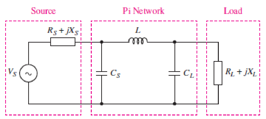
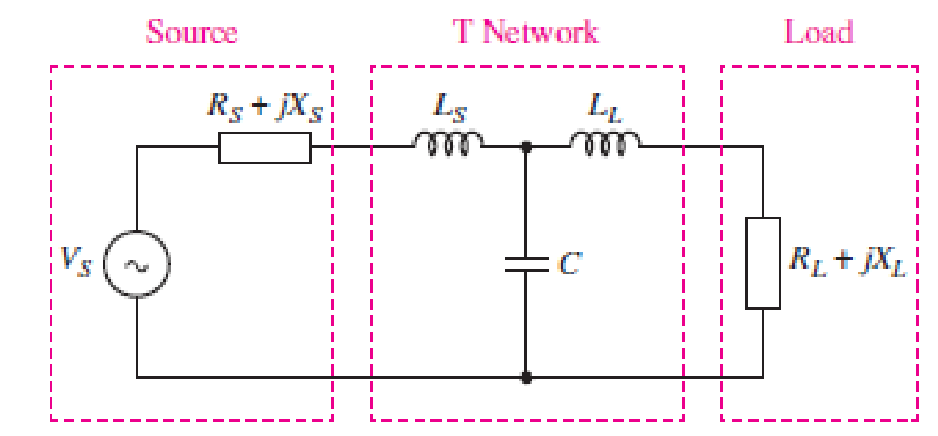
You would like to maximize power transfer to a 50 Ω antenna for VHF communications at 100 MHz. The source has an impedance of 10 + j5 Ω at this frequency. Design a T or Pi matching network for maximum power transfer (see Figs. 11.51 and 11.52). Simulate your design using SPICE, and use an appropriate supporting argument to verify maximum power transfer.
■ FIGURE 11.51
■ FIGURE 11.52
Expert Solution & Answer
Want to see the full answer?
Check out a sample textbook solution
Students have asked these similar questions
Course: Electrical Engineering
Subject: Electrical Apparatus
Instructions:
• Write the GIVEN with their respective symbols and units.
• Do not skip the SOLUTIONS, do it step-by-step with their respective
symbols and units
• Round up to 3 three decimal places the FINAL ANSWERS and BOx
it.
Problem:
For the following voltage and current phasors, calculate the
complex power, apparent power, real power, and reactive power.
Specify whether the pf is leading or lagging.
V = 220430° V rms, I = 0.5460° A rms
V = 16045° V rms, I = 8.50°A rms
1. A resistor of 50 ohms, a 200mH inductor, and a 1.5 x 10⁻⁴ F capacitor are connected in parallel
to a 120-volt, 60 cps source. Calculate: a) the equivalent impedance; b) the current in each load;
c) total current; d) the total real, reactive, and apparent powers; e) power factor.
(c) A 240 V rms 50 Hz supply serves four resistive loads that is 10 kW each, an
inductive load of 75 kVAR and a 45 kVAR capacitive load. Calculate :
(i)
The current drawn from the supply.
(ii)
The KVAR rating and capacitance required to improve the power factor to
0.95 lagging.
(iii) The current drawn from the supply after power factor correction.
Chapter 11 Solutions
Loose Leaf for Engineering Circuit Analysis Format: Loose-leaf
Ch. 11.1 - A current source of 12 cos 2000t A, a 200 ....Ch. 11.2 - Given the phasor voltage across an impedance ,...Ch. 11.2 - Prob. 3PCh. 11.2 - Prob. 4PCh. 11.2 - A voltage source vs is connected across a 4...Ch. 11.3 - If the 30 mH inductor of Example 11.7 is replaced...Ch. 11.4 - Calculate the effective value of each of the...Ch. 11.5 - For the circuit of Fig. 11.16, determine the power...Ch. 11.6 - Prob. 10PCh. 11 - Prob. 1E
Ch. 11 - Determine the power absorbed at t = 1.5 ms by each...Ch. 11 - Calculate the power absorbed at t = 0, t = 0+, and...Ch. 11 - Three elements are connected in parallel: a 1 k...Ch. 11 - Let is = 4u(t) A in the circuit of Fig. 11.28. (a)...Ch. 11 - Prob. 6ECh. 11 - Assuming no transients are present, calculate the...Ch. 11 - Prob. 8ECh. 11 - Prob. 9ECh. 11 - Prob. 10ECh. 11 - The phasor current I=915mA (corresponding to a...Ch. 11 - A phasor voltage V=10045V (the sinusoid operates...Ch. 11 - Prob. 13ECh. 11 - Prob. 14ECh. 11 - Find the average power for each element in the...Ch. 11 - (a) Calculate the average power absorbed by each...Ch. 11 - Prob. 17ECh. 11 - Prob. 18ECh. 11 - Prob. 19ECh. 11 - The circuit in Fig. 11.36 has a series resistance...Ch. 11 - Prob. 21ECh. 11 - Prob. 22ECh. 11 - Prob. 23ECh. 11 - Prob. 24ECh. 11 - Prob. 25ECh. 11 - Prob. 26ECh. 11 - Prob. 27ECh. 11 - Prob. 28ECh. 11 - Prob. 29ECh. 11 - Prob. 30ECh. 11 - Prob. 31ECh. 11 - Prob. 32ECh. 11 - Prob. 33ECh. 11 - (a) Calculate both the average and rms values of...Ch. 11 - Prob. 35ECh. 11 - FIGURE 11.43 Calculate the power factor of the...Ch. 11 - Prob. 37ECh. 11 - Prob. 38ECh. 11 - Prob. 40ECh. 11 - Prob. 41ECh. 11 - Prob. 42ECh. 11 - Prob. 43ECh. 11 - Compute the complex power S (in polar form) drawn...Ch. 11 - Calculate the apparent power, power factor, and...Ch. 11 - Prob. 46ECh. 11 - Prob. 48ECh. 11 - Prob. 49ECh. 11 - Prob. 50ECh. 11 - Prob. 51ECh. 11 - Prob. 52ECh. 11 - FIGURE 11.49 Instead of including a capacitor as...Ch. 11 - Prob. 54ECh. 11 - A load is drawing 10 A rms when connected to a...Ch. 11 - For the circuit of Fig. 11.50, assume the source...Ch. 11 - Prob. 57ECh. 11 - A source 45 sin 32t V is connected in series with...Ch. 11 - Prob. 60ECh. 11 - FIGURE 11.51 The circuit in Fig. 11.51 uses a Pi...Ch. 11 - Prob. 62ECh. 11 - Prob. 63ECh. 11 - You would like to maximize power transfer to a 50 ...
Knowledge Booster


Learn more about
Need a deep-dive on the concept behind this application? Look no further. Learn more about this topic, electrical-engineering and related others by exploring similar questions and additional content below.Similar questions
- Some parameters are given related to your student ID numbers. These are:V1 = XXX V (first 3 numbers, e.g. 170 V (RMS)) f1 = XXX Hz (assume that your last number is ‘y’, then f1 = (y+1)*10 Hz, e.g. if y=2 then f1=(2+1)*10=30Hz)1) A single-phase load has an active power of P = 2 kW at V1 V @f1Hz and the power factor is cosφ = 0.75. This motor iscompensated to cosφ = 0.85 using a parallel capacitor (the load is modelled as series RL). Determine:a. Reactive power and apparent power before compensation using power factorb. Current before compensationc. R, XL and L values of the loadd. Reactive power and apparent power after compensatione. Find the reactive power difference between compensated and uncompensated status (which will give thecapacitor power) and calculate XC and C using the power difference valuef. Simulate the uncompensated and compensated circuits. Plot voltage and current on components andcalculate the phase shift of the signals from Ving. Plot Vin and Iin comparison for…arrow_forwardA resistor of 6 ohms and an unknown impedance coil in series draws 12 A from a 120 V, 60 Hz line. If the real power taken from the line is 1152 Watts, what is the coil inductance?arrow_forwardA source supplies power to the following three loads connected in parallel: (1) a lighting load drawing 10 kW, (2) an induction motor drawing 10 kVA at 0.90 power factor lagging, and (3) a synchronous motor operating at 10 hp, 85% efficiency and 0.95 power factor leading (1 hp 0.746 kW). Determine the real, reactive, and apparent power delivered by the source. Also, draw the source power triangle.arrow_forward
- 2 A 213V 60Hz supply drives a load with an impedance of 28<45°ohms. What is the real power in watts? Note: answer value to be in integer form, (approximation to zero decimal point) 2 Question 7 W S # 3 с E D $ 4 R F G Search or type URL % 5 T G 6 MacBook Pro Y * H & 7 U * 00 8 J 1 ( 9 K ) 1 O 4 O P { + 11 [ = 11 1arrow_forwardFor the circuit shown in Fig Q2, determine: (a) The total impedance seen by the source. (b) The total supply current (1) (c) The voltage across the capacitors (Ve) (d) The active power, reactive power and power factor of the source. R₁5602 E = 100V 200 560 + fr = 400 R₂200 + Ve Fig. Q2 Xc₁ = 400arrow_forwardL3 12 teeet 1.25 mF 40 mH R1 3Ω 30 mH R3 Is 1 mF C2 Vc2 Vs 340 sin (200t) Figure 2 3) As referred to Figure 2, determine these quantities: a) Average power, P delivered by the voltage source. b) Total reactive power, Q consumed by the inductors and capacitors. c) Complex power of the circuit. leeearrow_forward
- Transmission Power Lines Tutorials Tutorial n° 0: Construction of transmission power lines A Young Electrical Engineer proposes to build an electrical network with a starting voltage of 110 kV to supply a city with a power of 15 MW. He finds that his power line changes direction 8 times in its journey. The distance between the first support and the 1st change of direction is 3.5 km. Between the 2nd and the 3rd change of direction the distance is 5 km, while between the 6th and the 7th it is 4 km. The distances between the other changes of direction are 3 km. At the 4th change of direction, the line finds a branch to supply a 1.5 MVA load at station B located 6 km away. The distance between the last support and the last change of direction is 3.5 km. This line crosses a busy road three times. The distance between two supports is 250 m and the distance between two consecutive electrical crossing supports is 150m. The definition and the diagram of the layout, canton, range, arrow of the…arrow_forwardA voltage of 10020° V(rms) is across an impedance of 5 + j2 №. a) What type of impedance is this (capacitive, inductive, or purely resistive)? b) Determine the current in the circuit; c) Draw the phasor diagram showing voltage and current; what is the phase relationship between current and voltage? Is this consistent with your answer to part a)? d) Determine the apparent, real, and reactive power delivered to the load; draw the power triangle; what is the power factor angle? What is the power factor (don't forget to include leading/lagging)?arrow_forwardA 3-phase, 50 Hz, 3000 V motor develops 600 H.P. (447·6 kW), the power factor being 0·75 lagging and the efficiency 0·93. A bank of capacitors is connected in delta across the supply terminals and power factor raised to 0·9 lagging. Each of the capacitance units is built of five similar 600-V capacitors. Determine the leading Kvar taken by each three sets.arrow_forward
- Example 11.8. An alternating current is given by; i = 10 sin 942 t Determine the time taken from t = 0 for the current to reach a value of + 6 A for a first and second time.arrow_forwardUsing the Illustration below. Compute the total impedance (Z), the total current (I), the voltage drop across R. the voltage drop across ??, the voltage drop across ??, the true or useful power (P), the reactive power (Q) and the apparent power (S). (Answer it with a complete solution)arrow_forwardGiven a series circuit comprised of the following element: 77.03-ohm resistor, practical inductor with internal resistance of 0.16 ohm and reactance of 74.36 ohms; and a capacitor with reactance of 12.45 ohms. Compute for the magnitude of its equivalent impedance in ohms. Note: Follow this reminder carefully. Compute to the nearest 4 decimal places. No Scientific notation. Do not round off in the middle of calculation. Use stored values.arrow_forward
arrow_back_ios
SEE MORE QUESTIONS
arrow_forward_ios
Recommended textbooks for you
 Introductory Circuit Analysis (13th Edition)Electrical EngineeringISBN:9780133923605Author:Robert L. BoylestadPublisher:PEARSON
 Delmar's Standard Textbook Of ElectricityElectrical EngineeringISBN:9781337900348Author:Stephen L. HermanPublisher:Cengage Learning
 Programmable Logic ControllersElectrical EngineeringISBN:9780073373843Author:Frank D. PetruzellaPublisher:McGraw-Hill Education
 Fundamentals of Electric CircuitsElectrical EngineeringISBN:9780078028229Author:Charles K Alexander, Matthew SadikuPublisher:McGraw-Hill Education
 Electric Circuits. (11th Edition)Electrical EngineeringISBN:9780134746968Author:James W. Nilsson, Susan RiedelPublisher:PEARSON
 Engineering ElectromagneticsElectrical EngineeringISBN:9780078028151Author:Hayt, William H. (william Hart), Jr, BUCK, John A.Publisher:Mcgraw-hill Education,
Introductory Circuit Analysis (13th Edition)
Electrical Engineering
ISBN:9780133923605
Author:Robert L. Boylestad
Publisher:PEARSON
Delmar's Standard Textbook Of Electricity
Electrical Engineering
ISBN:9781337900348
Author:Stephen L. Herman
Publisher:Cengage Learning
Programmable Logic Controllers
Electrical Engineering
ISBN:9780073373843
Author:Frank D. Petruzella
Publisher:McGraw-Hill Education
Fundamentals of Electric Circuits
Electrical Engineering
ISBN:9780078028229
Author:Charles K Alexander, Matthew Sadiku
Publisher:McGraw-Hill Education
Electric Circuits. (11th Edition)
Electrical Engineering
ISBN:9780134746968
Author:James W. Nilsson, Susan Riedel
Publisher:PEARSON
Engineering Electromagnetics
Electrical Engineering
ISBN:9780078028151
Author:Hayt, William H. (william Hart), Jr, BUCK, John A.
Publisher:Mcgraw-hill Education,
Types of Energy for Kids - Renewable and Non-Renewable Energies; Author: Smile and Learn - English;https://www.youtube.com/watch?v=w16-Uems2Qo;License: Standard Youtube License