
Loose Leaf for Engineering Circuit Analysis Format: Loose-leaf
9th Edition
ISBN: 9781259989452
Author: Hayt
Publisher: Mcgraw Hill Publishers
expand_more
expand_more
format_list_bulleted
Concept explainers
Videos
Textbook Question
Chapter 11, Problem 16E
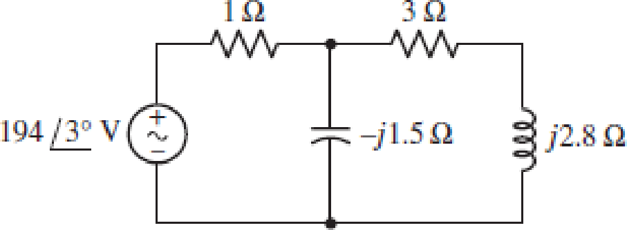
(a) Calculate the average power absorbed by each passive element in the circuit of Fig. 11.33, and verify that it equals the average power supplied by the source. (b) Check your solution with an appropriate SPICE simulation.
FIGURE 11.33
Expert Solution & Answer
Want to see the full answer?
Check out a sample textbook solution
Students have asked these similar questions
Fig. 11.1 shows a circuit that switches on a warning lamp when the temperature in an
oven falls below a set value.
thermistor
warning
Лamp
Fig. 11.1
Explain, with reference to the components in the circuit and point P,
(i) why the warning lamp is on when the temperature in the oven is below the set value,
Section 11.8
Power Factor Correction
11.69 Refer to the circuit shown in Fig. 11.88.
(a) What is the power factor?
(b) What is the average power dissipated?
(c) What is the value of the capacitance that will give
a unity power factor when connected to the load?
120 V rms
Z 10 +j122
60 Hz
11.19 The variable resistor R in the circuit of Fig. 11.50 is
adjusted until it absorbs the maximum average
power. Find R and the maximum average power
absorbed.
j1Ω 3
Figure 11.50
For Prob. 11.19.
392
www
4/0° A
wwww
-j2Q2
692
R
Chapter 11 Solutions
Loose Leaf for Engineering Circuit Analysis Format: Loose-leaf
Ch. 11.1 - A current source of 12 cos 2000t A, a 200 ....Ch. 11.2 - Given the phasor voltage across an impedance ,...Ch. 11.2 - Prob. 3PCh. 11.2 - Prob. 4PCh. 11.2 - A voltage source vs is connected across a 4...Ch. 11.3 - If the 30 mH inductor of Example 11.7 is replaced...Ch. 11.4 - Calculate the effective value of each of the...Ch. 11.5 - For the circuit of Fig. 11.16, determine the power...Ch. 11.6 - Prob. 10PCh. 11 - Prob. 1E
Ch. 11 - Determine the power absorbed at t = 1.5 ms by each...Ch. 11 - Calculate the power absorbed at t = 0, t = 0+, and...Ch. 11 - Three elements are connected in parallel: a 1 k...Ch. 11 - Let is = 4u(t) A in the circuit of Fig. 11.28. (a)...Ch. 11 - Prob. 6ECh. 11 - Assuming no transients are present, calculate the...Ch. 11 - Prob. 8ECh. 11 - Prob. 9ECh. 11 - Prob. 10ECh. 11 - The phasor current I=915mA (corresponding to a...Ch. 11 - A phasor voltage V=10045V (the sinusoid operates...Ch. 11 - Prob. 13ECh. 11 - Prob. 14ECh. 11 - Find the average power for each element in the...Ch. 11 - (a) Calculate the average power absorbed by each...Ch. 11 - Prob. 17ECh. 11 - Prob. 18ECh. 11 - Prob. 19ECh. 11 - The circuit in Fig. 11.36 has a series resistance...Ch. 11 - Prob. 21ECh. 11 - Prob. 22ECh. 11 - Prob. 23ECh. 11 - Prob. 24ECh. 11 - Prob. 25ECh. 11 - Prob. 26ECh. 11 - Prob. 27ECh. 11 - Prob. 28ECh. 11 - Prob. 29ECh. 11 - Prob. 30ECh. 11 - Prob. 31ECh. 11 - Prob. 32ECh. 11 - Prob. 33ECh. 11 - (a) Calculate both the average and rms values of...Ch. 11 - Prob. 35ECh. 11 - FIGURE 11.43 Calculate the power factor of the...Ch. 11 - Prob. 37ECh. 11 - Prob. 38ECh. 11 - Prob. 40ECh. 11 - Prob. 41ECh. 11 - Prob. 42ECh. 11 - Prob. 43ECh. 11 - Compute the complex power S (in polar form) drawn...Ch. 11 - Calculate the apparent power, power factor, and...Ch. 11 - Prob. 46ECh. 11 - Prob. 48ECh. 11 - Prob. 49ECh. 11 - Prob. 50ECh. 11 - Prob. 51ECh. 11 - Prob. 52ECh. 11 - FIGURE 11.49 Instead of including a capacitor as...Ch. 11 - Prob. 54ECh. 11 - A load is drawing 10 A rms when connected to a...Ch. 11 - For the circuit of Fig. 11.50, assume the source...Ch. 11 - Prob. 57ECh. 11 - A source 45 sin 32t V is connected in series with...Ch. 11 - Prob. 60ECh. 11 - FIGURE 11.51 The circuit in Fig. 11.51 uses a Pi...Ch. 11 - Prob. 62ECh. 11 - Prob. 63ECh. 11 - You would like to maximize power transfer to a 50 ...
Knowledge Booster


Learn more about
Need a deep-dive on the concept behind this application? Look no further. Learn more about this topic, electrical-engineering and related others by exploring similar questions and additional content below.Similar questions
- For the circuit of Fig.11.78 composed of standard values: A. Determine the time constant. B. Write the mathematical expression for the current It after the switch is closed C. Repeat part (b) for VL and VR D. Determine il and VL at one three- and five-time constants. E. Sketch the waveforms of iL,VL and VR.arrow_forwardFor the circuit of Fig. 11.50, assume the source operates at a frequency of 100 rad/s. (a) Determine the PF at which the source is operating. (b) Cal- culate the apparent power absorbed by each of the three passive elements. (c) Compute the average power supplied by the source. (d) Determine the Thévenin equivalent seen looking into the terminals marked a and b, and calculate the average power delivered to a 100 2 resistor connected between the same terminals. j60 92 ell FIGURE 11.50 w 50 2 5/0° A www 80 Ω 02 obarrow_forwardAnswer 11.30arrow_forward
- 11.15 In the circuit of Fig. 11.46, find the value of Z, that will absorb the maximum power and the value of the maximum power. 120/0° V 192 wwwww --/12 V./19 V₂ 2V₂ ZLarrow_forward11.85 A regular household system of a single-phase three- wire circuit allows the operation of both 120-V and 240-V, 60-Hz appliances. The household circuit is modeled as shown in Fig. 11.96. Calculate: (a) the currents I₁, I₂, and I, (b) the total complex power supplied (c) the overall power factor of the circuit 120/0° V 120/0° V In 1₂ 10 22 10 Ω 15 mH wwww wwwm Lamp 30 92 Refrigerator www Kitchen ramparrow_forwardRefer to the circuit shown in Fig. 11.88. (a) What is the power factor? (b) What is the average power dissipated? (c) What is the value of the capacitance that will give a unity power factor when connected to the load? 120 V rms 60 Hz Ζ = 10 + j 12 Ωarrow_forward
- Asaparrow_forward11.6 For the circuit in Fig. 11.38, i, = 6 cos 10³t A. Find the average power absorbed by the 50-2 resistor. is Figure 11.38 For Prob. 11.6. www 20ix + 50 Ω 40 μF 20 mH 10 S2arrow_forwardIn Fig. 11.12, the resistor R, is adjusted until it absorbs the maximum average power. Calculate R, and the maximum average power absorbed by it. 80 42 j60 2 120/60° V -/30 2 Figure 11.12 For Practice Prob. 11.6. Answer: 300, 6.863 W. 90 £2 Practice Problem 11.6arrow_forward
- 11.51 For the entire circuit in Fig. 11.70, calculate: (a) the power factor (b) the average power delivered by the source (c) the reactive power (d) the apparent power (e) the complex power 50/50° V (+) Figure 11.70 For Prob. 11.51. 292 www ww -j5Q 10 92 ele j6 Ω 892arrow_forward11.51 For the entire circuit in Fig. 11.70, calculate: (a) the power factor (b) the average power delivered by the source (c) the reactive power (d) the apparent power (e) the complex power ww j62 16/45° V 10Ω 8Ωarrow_forward11.75 Consider the power system shown in Fig. 11.90. Calculate: (a) the total complex power (b) the power factor (c) the parallel capacitance necessary to establish a unity power factor O- + 240 V rms, 50 Hz - Figure 11.90 For Prob. 11.75. 80-j50 92 120 + j70 Ω 60+j0 22arrow_forward
arrow_back_ios
SEE MORE QUESTIONS
arrow_forward_ios
Recommended textbooks for you
 Introductory Circuit Analysis (13th Edition)Electrical EngineeringISBN:9780133923605Author:Robert L. BoylestadPublisher:PEARSON
 Delmar's Standard Textbook Of ElectricityElectrical EngineeringISBN:9781337900348Author:Stephen L. HermanPublisher:Cengage Learning
 Programmable Logic ControllersElectrical EngineeringISBN:9780073373843Author:Frank D. PetruzellaPublisher:McGraw-Hill Education
 Fundamentals of Electric CircuitsElectrical EngineeringISBN:9780078028229Author:Charles K Alexander, Matthew SadikuPublisher:McGraw-Hill Education
 Electric Circuits. (11th Edition)Electrical EngineeringISBN:9780134746968Author:James W. Nilsson, Susan RiedelPublisher:PEARSON
 Engineering ElectromagneticsElectrical EngineeringISBN:9780078028151Author:Hayt, William H. (william Hart), Jr, BUCK, John A.Publisher:Mcgraw-hill Education,
Introductory Circuit Analysis (13th Edition)
Electrical Engineering
ISBN:9780133923605
Author:Robert L. Boylestad
Publisher:PEARSON
Delmar's Standard Textbook Of Electricity
Electrical Engineering
ISBN:9781337900348
Author:Stephen L. Herman
Publisher:Cengage Learning
Programmable Logic Controllers
Electrical Engineering
ISBN:9780073373843
Author:Frank D. Petruzella
Publisher:McGraw-Hill Education
Fundamentals of Electric Circuits
Electrical Engineering
ISBN:9780078028229
Author:Charles K Alexander, Matthew Sadiku
Publisher:McGraw-Hill Education
Electric Circuits. (11th Edition)
Electrical Engineering
ISBN:9780134746968
Author:James W. Nilsson, Susan Riedel
Publisher:PEARSON
Engineering Electromagnetics
Electrical Engineering
ISBN:9780078028151
Author:Hayt, William H. (william Hart), Jr, BUCK, John A.
Publisher:Mcgraw-hill Education,
How Electric Motors Work - 3 phase AC induction motors ac motor; Author: The Engineering Mindset;https://www.youtube.com/watch?v=59HBoIXzX_c;License: Standard Youtube License