
Loose Leaf for Engineering Circuit Analysis Format: Loose-leaf
9th Edition
ISBN: 9781259989452
Author: Hayt
Publisher: Mcgraw Hill Publishers
expand_more
expand_more
format_list_bulleted
Concept explainers
Videos
Textbook Question
Chapter 7.2, Problem 5P
The current waveform of Fig. 7.14a has equal rise and fall times of duration 0.1 s (100 ms). Calculate the maximum positive and negative voltages across the same inductor if the rise and fall times, respectively, are changed to (a) 1 ms, 1 ms; (b) 12 μs, 64 μs; (c) 1 s, 1 ns.
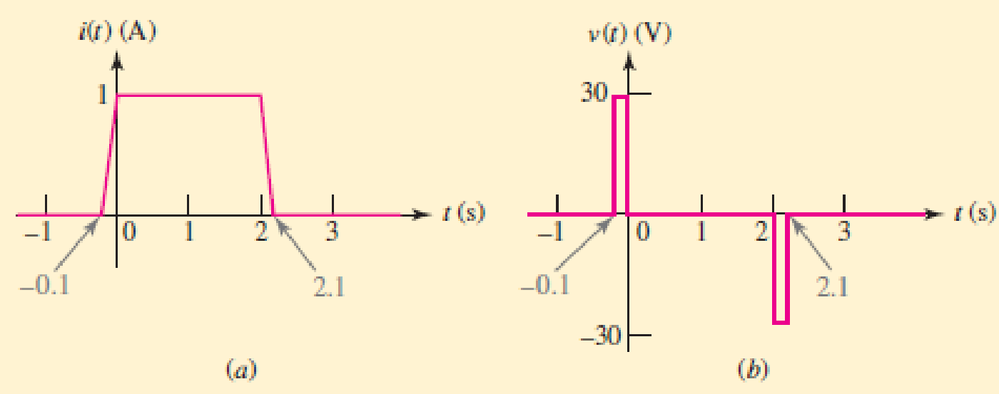
■ FIGURE 7.14 (a) The time required for the current of Fig. 7.12a to change from 0 to 1 and from 1 to 0 is decreased by a factor of 10. (b) The resultant voltage waveform. The pulse widths are exaggerated for clarity.
Expert Solution & Answer
Want to see the full answer?
Check out a sample textbook solution
Students have asked these similar questions
7.49.2 For the RC circuit shown in the image below, the current waveform is applied.
If v (0) = 0, R1 = 4 S2 and R2 = 9 $2, determine the voltage across the capacitor, v
when t = 1.1 s. Please pay attention: the numbers may change since they are
randomized. Your answer must include 3 places after the decimal point, and the
proper SI unit.
is (A) A
1
t (s)
(a)
R2
+
is
R,
0.5 F
(b)
Your Answer:
Answer
units
Q7. (a) Calculate the equivalent inductance of the circuit shown in Figure Q7a.O
2mH
3mH
L3
L2
L,34mH
L43 2mH
Figure Q7a
(b) In the circuit shown in Figure Q7b, R = 10 N and L = 1.5 H. The switch is
%3D
%3D
closed at time t =
0.
R.
25V
Figure Q7b
(i) Determine the voltage across the inductor at t = 10 ms.
(ii) Calculate the time, t, at which the energy stored in the inductor is 4 J.
(iii) Determine the value of current at the instant of switch on.
(iv) Determine the final (steady-state) value of the current.
(v) Calculate the rate of change of the current at the instant of switch on.
00
Example 7.33. Two coils of inductances 4 and 6 henry are connected in parallel. If their
mutual inductance is 3 henry, calculate the equivalent inductance of the combination if (i) mutual
inductance assists the self-inductance (ii) mutual inductance opposes the self-inductance.
Chapter 7 Solutions
Loose Leaf for Engineering Circuit Analysis Format: Loose-leaf
Ch. 7.1 - Determine the current flowing through a 5 mF...Ch. 7.1 - Prob. 2PCh. 7.1 - Prob. 3PCh. 7.2 - 7.4 The current through a 200 mH inductor is shown...Ch. 7.2 - The current waveform of Fig. 7.14a has equal rise...Ch. 7.2 - Prob. 6PCh. 7.2 - Let L = 25 mH for the inductor of Fig. 7.10. (a)...Ch. 7.3 - Find Ceq for the network of Fig. 7.23. FIGURE...Ch. 7.4 - If vC(t) = 4 cos 105t V in the circuit in Fig....Ch. 7.5 - Derive an expression for vout in terms of vs for...
Ch. 7.6 - Prob. 11PCh. 7 - Making use of the passive sign convention,...Ch. 7 - Prob. 2ECh. 7 - (a) If the voltage waveform depicted in Fig. 7.42...Ch. 7 - A capacitor is constructed from two brass plates,...Ch. 7 - Prob. 5ECh. 7 - Prob. 6ECh. 7 - Design a capacitor whose capacitance can be varied...Ch. 7 - Design a capacitor whose capacitance can be varied...Ch. 7 - Prob. 9ECh. 7 - Assuming the passive sign convention, sketch the...Ch. 7 - Prob. 11ECh. 7 - Prob. 12ECh. 7 - Prob. 13ECh. 7 - Calculate the power dissipated in the 40 resistor...Ch. 7 - Prob. 15ECh. 7 - Design a 30 nH inductor using 28 AWG solid soft...Ch. 7 - Prob. 17ECh. 7 - Prob. 18ECh. 7 - Prob. 19ECh. 7 - Prob. 20ECh. 7 - Calculate vL and iL for each of the circuits...Ch. 7 - The current waveform shown in Fig. 7.14 has a rise...Ch. 7 - Determine the inductor voltage which results from...Ch. 7 - Prob. 24ECh. 7 - The voltage across a 2 H inductor is given by vL =...Ch. 7 - Calculate the energy stored in a 1 nH inductor if...Ch. 7 - Determine the amount of energy stored in a 33 mH...Ch. 7 - Making the assumption that the circuits in Fig....Ch. 7 - Calculate the voltage labeled vx in Fig. 7.52,...Ch. 7 - Prob. 30ECh. 7 - Prob. 31ECh. 7 - Determine an equivalent inductance for the network...Ch. 7 - Using as many 1 nH inductors as you like, design...Ch. 7 - Compute the equivalent capacitance Ceq as labeled...Ch. 7 - Prob. 35ECh. 7 - Prob. 36ECh. 7 - Reduce the circuit depicted in Fig. 7.59 to as few...Ch. 7 - Refer to the network shown in Fig. 7.60 and find...Ch. 7 - Prob. 39ECh. 7 - Prob. 40ECh. 7 - Prob. 41ECh. 7 - Prob. 42ECh. 7 - Prob. 43ECh. 7 - Prob. 44ECh. 7 - Prob. 45ECh. 7 - Prob. 46ECh. 7 - Prob. 47ECh. 7 - Let vs = 100e80t V with no initial energy stored...Ch. 7 - Prob. 49ECh. 7 - Prob. 50ECh. 7 - Interchange the location of R1 and Cf in the...Ch. 7 - For the integrating amplifier circuit of Fig....Ch. 7 - Prob. 53ECh. 7 - For the circuit shown in Fig. 7.73, assume no...Ch. 7 - A new piece of equipment designed to make crystals...Ch. 7 - An altitude sensor on a weather balloon provides a...Ch. 7 - One problem satellites face is exposure to...Ch. 7 - The output of a velocity sensor attached to a...Ch. 7 - A floating sensor in a certain fuel tank is...Ch. 7 - (a) If Is = 3 sin t A, draw the exact dual of the...Ch. 7 - Draw the exact dual of the simple circuit shown in...Ch. 7 - (a) Draw the exact dual of the simple circuit...Ch. 7 - (a) Draw the exact dual of the simple circuit...Ch. 7 - Prob. 64ECh. 7 - Prob. 65ECh. 7 - Prob. 66ECh. 7 - Prob. 67ECh. 7 - Prob. 68ECh. 7 - Prob. 69ECh. 7 - Prob. 70ECh. 7 - For the circuit of Fig. 7.28, (a) sketch vout over...Ch. 7 - (a) Sketch the output function vout of the...Ch. 7 - For the circuit of Fig. 7.72, (a) sketch vout over...
Knowledge Booster


Learn more about
Need a deep-dive on the concept behind this application? Look no further. Learn more about this topic, electrical-engineering and related others by exploring similar questions and additional content below.Similar questions
- A Hays bridge is often used for measuring the inductance of high Q coils and has theconfiguration shown in Figure 7.22. The inductance and resistance of the coil arerepresented in the figure by the symbols L1 and R1, respectively. (a) Obtain the bridge balance conditions.(b) Show that if the Q value of an unknown inductor coil is high, the expressionfor the inductance value when the bridge is balanced is independent offrequency.(c) If the Q value is high, calculate the value of the inductor if the bridge component values at balance are as follows: R2 = R3 = 1000 ohm ; C =0.02 mFarrow_forwardDetermine an equivalent inductance for the network shown in Fig. 7.54 if each inductor has value L. ell rell rell ellarrow_forwardA 2.5-µH inductor has a resistance of 23 V. At a frequency of 35 MHz, find its Q. (round-off your answer to whole number with correct unit) *arrow_forward
- When the switch is closed in this circuit, a battery of value 10 V begins charging a capacitor of value 10 μF, through a resistor of value 20 kn. C R At a certain instant of time, the current charging the capacitor has the value i = 0.2 mA. (a) What magnitude of charge is stored on each of this capacitor's plates at that instant of time? (Include appropriate units.) (b) What magnitude of charge will be stored on each of this capacitor's plates a very long time after the switch is closed? Submit Answerarrow_forwardA suspension string has 3 units. Each unit can withstand a maximum peak voltage of 11kV. The capacitance of each joint and metal work is 20% of the capacitance od each disc. Find (i) maximum line voltage for which the string can be used. (ii) string efficiencyarrow_forward1. It is the variation in capacitance express as a percentage of its specified value at 25 degrees Celsius where 25 degrees is referred to as nominal Value. 2. Farad is the SI unit of Capacitance. A capacitor has a capacitance of 1 Farad if 3. It is device that stores electric energy, previously called condenser. 4. Name the 3 broad categories of Capacitor. 5. It is expresses the ratio of energy wasted to the energy stored in a capacitor. 6. It is the maximum capacitor voltage that causes the dielectric to become damage... 7. A two terminal devices that consist of a coiled wire wound in a common core or in a free air. 8. It is measure of how much counter emf is generated in a circuit. 9. Henry is the unit of inductance. Name after the American physicist. 10. It is the condition of inducing an emf in a coil by magnetic fluc generated in another coil.arrow_forward
- The current in a 10-mH inductor has the waveform shown i(t) (mA) 20 2 4 t (ms) a) the voltage induced across the inductor between 0 to 2ms is b) the voltage induced across the inductor between 2 to 4ms is Answer must be in numeral form. No decimal point. mV mVarrow_forward1) Determine the Capacitance value to calculate the time constant of the circuit.2) Determine the time constant of the circuit for the capacities you have determined.3) For the capacity value, calculate the estimated time to come to the final state.4) Plot capacitor current and voltage graphs and show if it works in harmony with the time constant you calculated.NOTE: if you want you can use falstad online circuit simulator.arrow_forwardQuestion 32 Determine an equivalent inductance for the network shown in Fig. 7.54 if each inductor has value L. O rele Ay ell FIGURE 7.54 rellarrow_forward
- A capacitor sensor consists of 3 charged parallel plates have breath of 500 mm. These plates are separated from each other by 7.5 mm. When, the middle plate is moving up by 0.25 mm. Assuming upper and lower plates kept fixed, calculate the following, i. Length of the capacitor plates, if the total change in capacitance is 1.190 pF ii. Values of C1 and C2.arrow_forwardCapacitance= 7uF Determine the time constant of the circuit for the capacities. For the capacity value, calculate the estimated time to come to the final state. Plot capacitor current and voltage graphs and show if it works in harmony with the time constant you calculated. NOTE: if you want you can use falstad online circuit simulator.arrow_forwardIn your solution, follow the sequence: Given, unknown, solution, and final answer. BOX your final answers. thank you! 7. A 120 Hz 20 mA ac current is present in a 10H inductor. What is the reactance of the inductor and the voltage drop across the inductor?arrow_forward
arrow_back_ios
SEE MORE QUESTIONS
arrow_forward_ios
Recommended textbooks for you
 Introductory Circuit Analysis (13th Edition)Electrical EngineeringISBN:9780133923605Author:Robert L. BoylestadPublisher:PEARSON
 Delmar's Standard Textbook Of ElectricityElectrical EngineeringISBN:9781337900348Author:Stephen L. HermanPublisher:Cengage Learning
 Programmable Logic ControllersElectrical EngineeringISBN:9780073373843Author:Frank D. PetruzellaPublisher:McGraw-Hill Education
 Fundamentals of Electric CircuitsElectrical EngineeringISBN:9780078028229Author:Charles K Alexander, Matthew SadikuPublisher:McGraw-Hill Education
 Electric Circuits. (11th Edition)Electrical EngineeringISBN:9780134746968Author:James W. Nilsson, Susan RiedelPublisher:PEARSON
 Engineering ElectromagneticsElectrical EngineeringISBN:9780078028151Author:Hayt, William H. (william Hart), Jr, BUCK, John A.Publisher:Mcgraw-hill Education,
Introductory Circuit Analysis (13th Edition)
Electrical Engineering
ISBN:9780133923605
Author:Robert L. Boylestad
Publisher:PEARSON
Delmar's Standard Textbook Of Electricity
Electrical Engineering
ISBN:9781337900348
Author:Stephen L. Herman
Publisher:Cengage Learning
Programmable Logic Controllers
Electrical Engineering
ISBN:9780073373843
Author:Frank D. Petruzella
Publisher:McGraw-Hill Education
Fundamentals of Electric Circuits
Electrical Engineering
ISBN:9780078028229
Author:Charles K Alexander, Matthew Sadiku
Publisher:McGraw-Hill Education
Electric Circuits. (11th Edition)
Electrical Engineering
ISBN:9780134746968
Author:James W. Nilsson, Susan Riedel
Publisher:PEARSON
Engineering Electromagnetics
Electrical Engineering
ISBN:9780078028151
Author:Hayt, William H. (william Hart), Jr, BUCK, John A.
Publisher:Mcgraw-hill Education,
ENA 9.2(1)(En)(Alex) Sinusoids & Phasors - Explanation with Example 9.1 ,9.2 & PP 9.2; Author: Electrical Engineering Academy;https://www.youtube.com/watch?v=vX_LLNl-ZpU;License: Standard YouTube License, CC-BY
Electrical Engineering: Ch 10 Alternating Voltages & Phasors (8 of 82) What is a Phasor?; Author: Michel van Biezen;https://www.youtube.com/watch?v=2I1tF3ixNg0;License: Standard Youtube License