
Loose Leaf for Engineering Circuit Analysis Format: Loose-leaf
9th Edition
ISBN: 9781259989452
Author: Hayt
Publisher: Mcgraw Hill Publishers
expand_more
expand_more
format_list_bulleted
Concept explainers
Videos
Textbook Question
Chapter 7, Problem 21E
Calculate vL and iL for each of the circuits depicted in Fig. 7.49 if is = 1 mA and vs = 2 V.
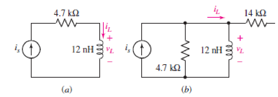
■ FIGURE 7.49
Expert Solution & Answer
Want to see the full answer?
Check out a sample textbook solution
Students have asked these similar questions
. Calculate v, and i̟ for each of the circuits depicted in Fig. 7.48, if i, = 1 mA
and v, = 2.1 V.
iL
14 kN
is
12 nH
4.7 kN
ll
Determine vo for the circuit shown in Figure 7.98(a) and (b).
12 V
Si
22 ka
Si
1.8 k2
10 k2
-12 V
(a)
(b)
Figure 7.8
Rp
->
sa
Figure 7.52 Bia
resistance, RG
Chapter 7 Solutions
Loose Leaf for Engineering Circuit Analysis Format: Loose-leaf
Ch. 7.1 - Determine the current flowing through a 5 mF...Ch. 7.1 - Prob. 2PCh. 7.1 - Prob. 3PCh. 7.2 - 7.4 The current through a 200 mH inductor is shown...Ch. 7.2 - The current waveform of Fig. 7.14a has equal rise...Ch. 7.2 - Prob. 6PCh. 7.2 - Let L = 25 mH for the inductor of Fig. 7.10. (a)...Ch. 7.3 - Find Ceq for the network of Fig. 7.23. FIGURE...Ch. 7.4 - If vC(t) = 4 cos 105t V in the circuit in Fig....Ch. 7.5 - Derive an expression for vout in terms of vs for...
Ch. 7.6 - Prob. 11PCh. 7 - Making use of the passive sign convention,...Ch. 7 - Prob. 2ECh. 7 - (a) If the voltage waveform depicted in Fig. 7.42...Ch. 7 - A capacitor is constructed from two brass plates,...Ch. 7 - Prob. 5ECh. 7 - Prob. 6ECh. 7 - Design a capacitor whose capacitance can be varied...Ch. 7 - Design a capacitor whose capacitance can be varied...Ch. 7 - Prob. 9ECh. 7 - Assuming the passive sign convention, sketch the...Ch. 7 - Prob. 11ECh. 7 - Prob. 12ECh. 7 - Prob. 13ECh. 7 - Calculate the power dissipated in the 40 resistor...Ch. 7 - Prob. 15ECh. 7 - Design a 30 nH inductor using 28 AWG solid soft...Ch. 7 - Prob. 17ECh. 7 - Prob. 18ECh. 7 - Prob. 19ECh. 7 - Prob. 20ECh. 7 - Calculate vL and iL for each of the circuits...Ch. 7 - The current waveform shown in Fig. 7.14 has a rise...Ch. 7 - Determine the inductor voltage which results from...Ch. 7 - Prob. 24ECh. 7 - The voltage across a 2 H inductor is given by vL =...Ch. 7 - Calculate the energy stored in a 1 nH inductor if...Ch. 7 - Determine the amount of energy stored in a 33 mH...Ch. 7 - Making the assumption that the circuits in Fig....Ch. 7 - Calculate the voltage labeled vx in Fig. 7.52,...Ch. 7 - Prob. 30ECh. 7 - Prob. 31ECh. 7 - Determine an equivalent inductance for the network...Ch. 7 - Using as many 1 nH inductors as you like, design...Ch. 7 - Compute the equivalent capacitance Ceq as labeled...Ch. 7 - Prob. 35ECh. 7 - Prob. 36ECh. 7 - Reduce the circuit depicted in Fig. 7.59 to as few...Ch. 7 - Refer to the network shown in Fig. 7.60 and find...Ch. 7 - Prob. 39ECh. 7 - Prob. 40ECh. 7 - Prob. 41ECh. 7 - Prob. 42ECh. 7 - Prob. 43ECh. 7 - Prob. 44ECh. 7 - Prob. 45ECh. 7 - Prob. 46ECh. 7 - Prob. 47ECh. 7 - Let vs = 100e80t V with no initial energy stored...Ch. 7 - Prob. 49ECh. 7 - Prob. 50ECh. 7 - Interchange the location of R1 and Cf in the...Ch. 7 - For the integrating amplifier circuit of Fig....Ch. 7 - Prob. 53ECh. 7 - For the circuit shown in Fig. 7.73, assume no...Ch. 7 - A new piece of equipment designed to make crystals...Ch. 7 - An altitude sensor on a weather balloon provides a...Ch. 7 - One problem satellites face is exposure to...Ch. 7 - The output of a velocity sensor attached to a...Ch. 7 - A floating sensor in a certain fuel tank is...Ch. 7 - (a) If Is = 3 sin t A, draw the exact dual of the...Ch. 7 - Draw the exact dual of the simple circuit shown in...Ch. 7 - (a) Draw the exact dual of the simple circuit...Ch. 7 - (a) Draw the exact dual of the simple circuit...Ch. 7 - Prob. 64ECh. 7 - Prob. 65ECh. 7 - Prob. 66ECh. 7 - Prob. 67ECh. 7 - Prob. 68ECh. 7 - Prob. 69ECh. 7 - Prob. 70ECh. 7 - For the circuit of Fig. 7.28, (a) sketch vout over...Ch. 7 - (a) Sketch the output function vout of the...Ch. 7 - For the circuit of Fig. 7.72, (a) sketch vout over...
Knowledge Booster


Learn more about
Need a deep-dive on the concept behind this application? Look no further. Learn more about this topic, electrical-engineering and related others by exploring similar questions and additional content below.Similar questions
- Electromagnet, picture 2 is an example of doing Practice Exercise 7.7, thank you in advance.arrow_forwardQuestion 25: For the circuit shown in Figure 7.76, find: (a) the current and the potential difference for each resistor; (b) the potential difference VA - VB (the directions given to the currents in the figure are arbitrary). (c) Check that the net power supplied by the batteries is fully transformed into heat in the resistors. Answer: (a) I2= 3.00 A ; I2= 1.00 A, in the opposite direction of the figure ; I3= 4,00 A in the opposite direction of the figure; ∆VR1= 6.00 V ; ∆VR2= 5.00 V ; ∆VR3= 20.0 V ; (b) -20.0 V (c) 103W *Please show steps, formulas and explanation for my own understanding. Thank youarrow_forwardQuestion 11 The current flowing through a 33 mF capacitor is shown graphically in Fig. 7.43. a) Assuming the passive sign convention, sketch the resulting voltage waveform across the device. b) Compute the voltage at 300 ms, 600 ms, and 1.1 s. i(A) 8 4 0 0.2 0.4 0.6 0.8 1.0 1.2 1.4 FIGURE 7.43 1 (S)arrow_forward
- PROBLE M 7.15 Determine VOUT versus vIN for the circuit shown in Figure 7.8 Assume that the MOSFET operates in saturation and is characterized by the paramete K and VT. What is the value of VOUT when VỊN = 0? PROBLEM 7.16 Determine vo versus vị for the circuit shown in Figure 7.8 Assume that the MOSFET operates in saturation and is characterized by the paramete K and VT. What is the value of vo when vj = = 0?arrow_forward× 7:53 www.bartleby.com Homework Help is Here - Start Your Trial Now! Q SEARCH Textbook Question 个 R₁ = 7,2 kn Fig. 7.69 Chapter 7, Problem 6P The total resistance R+ for the network of Fig. 7.69. is 7.2 k Find the resistance R. R₁ vport Solution ASK R₁ il 5GE ncwa R₁ R₁ G ●●● → 2arrow_forwardQuestion 14 Calculate the power dissipated in the 40 22 resistor and the voltage labeled vc in each of the circuits depicted in Fig. 7.44. 40 Ω 1.2 V 22 02 (a) + "C 9.8 mF 1.2 V + VC 9.8 mF 22 Ω (b) ww 40 Ωarrow_forward
- Example 7.33. Two coils of inductances 4 and 6 henry are connected in parallel. If their mutual inductance is 3 henry, calculate the equivalent inductance of the combination if (i) mutual inductance assists the self-inductance (ii) mutual inductance opposes the self-inductance.arrow_forward2. For the fixed-bias configuration of Fig. 7.76, determine: a. Ipo and VGS using a purely mathematical approach. b. Repeat part (a) using a graphical approach and compare results. c. Find Vps, VD, VG, and Vs using the results of part (a). -3 V * 1.2 ΜΩ VGSQ 16 V 1 2.2 ΚΩ PROBLEMS Fixed-Bias Configuration 100 pss = 10 mA Vp = -4.5V 3. Given the measured value of V₁ in Fig. 7.77, determine: a. Ip. b. Vps. c. VGG VD=6V 12 V 2.2 kΩ ID VGS 10 = 1 (1 - Vec)² ID Vp + VDS Inss=8 mA Vp=-4 V FIG. 7.77 Problem 3. 1 ΜΩ -VGG 50arrow_forward5. Determine Vp and VGs for the fixed-bias configuration of Fig. 7.79. 18 V 2 k2 VD Ipss = 8 mA Ve =-4 V 2 ΜΩ 4 V FIG. 7.79 Problem 5.arrow_forward
- 32 12 VFRT→ 162 12 2 Figure 7.1 See Figure 7.1. What is the current through the 30 resistor? 1.33 A 0.33 A 2.0 A O 1.0 Aarrow_forwardExample 2. Find the equivalent capacitance seen at the terminals of the circuit in Figure 7. 50 μF Ceg 70 F Figure 7. Ans. 40uF 60 μF 20 μF 120 μFarrow_forwardA 100µF capacitor is connected in series with a 150volt voltmeter that has a resistance of 1,000 ohms per volt. Calculate the reading of the voltmeter at the instant when t equals the time constant following the closing if the switch that impresses 120volts on the circuit.arrow_forward
arrow_back_ios
SEE MORE QUESTIONS
arrow_forward_ios
Recommended textbooks for you
 Introductory Circuit Analysis (13th Edition)Electrical EngineeringISBN:9780133923605Author:Robert L. BoylestadPublisher:PEARSON
 Delmar's Standard Textbook Of ElectricityElectrical EngineeringISBN:9781337900348Author:Stephen L. HermanPublisher:Cengage Learning
 Programmable Logic ControllersElectrical EngineeringISBN:9780073373843Author:Frank D. PetruzellaPublisher:McGraw-Hill Education
 Fundamentals of Electric CircuitsElectrical EngineeringISBN:9780078028229Author:Charles K Alexander, Matthew SadikuPublisher:McGraw-Hill Education
 Electric Circuits. (11th Edition)Electrical EngineeringISBN:9780134746968Author:James W. Nilsson, Susan RiedelPublisher:PEARSON
 Engineering ElectromagneticsElectrical EngineeringISBN:9780078028151Author:Hayt, William H. (william Hart), Jr, BUCK, John A.Publisher:Mcgraw-hill Education,
Introductory Circuit Analysis (13th Edition)
Electrical Engineering
ISBN:9780133923605
Author:Robert L. Boylestad
Publisher:PEARSON
Delmar's Standard Textbook Of Electricity
Electrical Engineering
ISBN:9781337900348
Author:Stephen L. Herman
Publisher:Cengage Learning
Programmable Logic Controllers
Electrical Engineering
ISBN:9780073373843
Author:Frank D. Petruzella
Publisher:McGraw-Hill Education
Fundamentals of Electric Circuits
Electrical Engineering
ISBN:9780078028229
Author:Charles K Alexander, Matthew Sadiku
Publisher:McGraw-Hill Education
Electric Circuits. (11th Edition)
Electrical Engineering
ISBN:9780134746968
Author:James W. Nilsson, Susan Riedel
Publisher:PEARSON
Engineering Electromagnetics
Electrical Engineering
ISBN:9780078028151
Author:Hayt, William H. (william Hart), Jr, BUCK, John A.
Publisher:Mcgraw-hill Education,
ENA 9.2(1)(En)(Alex) Sinusoids & Phasors - Explanation with Example 9.1 ,9.2 & PP 9.2; Author: Electrical Engineering Academy;https://www.youtube.com/watch?v=vX_LLNl-ZpU;License: Standard YouTube License, CC-BY
Electrical Engineering: Ch 10 Alternating Voltages & Phasors (8 of 82) What is a Phasor?; Author: Michel van Biezen;https://www.youtube.com/watch?v=2I1tF3ixNg0;License: Standard Youtube License