
Concept explainers
Videos
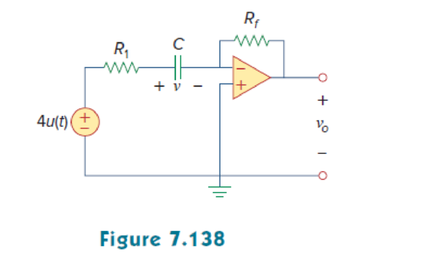
For the op amp circuit of Fig. 7.138, let R1 = 10 kΩ, Rf = 30 kΩ, C = 20 μF, and v(0) = 1 V. Find v0.
Find the output voltage
Answer to Problem 73P
The output voltage
Explanation of Solution
Given data:
Refer to Figure 7.138 in the textbook.
The value of capacitance
The source voltage
The value of resistance
The value of feedback resistance
The initial voltage v(0) or
Formula used:
Write the expression to find the time constant for an RC circuit.
Here,
C is the capacitance of the capacitor.
Write the general expression for the unit step function.
Calculation:
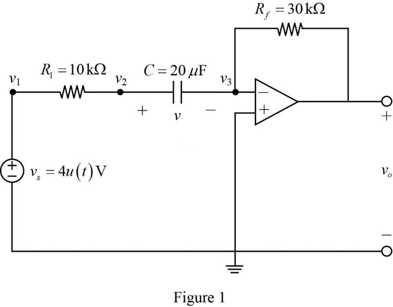
The given Figure 7.138 is redrawn as shown in Figure 1.
The given source voltage is,
Apply the unit step function in equation (2) to equation (3).
For
Since the source voltage
For
The source voltage is,
In Figure 1, apply Kirchhoff’s current law at node
In Figure 1, apply Kirchhoff’s current law at node
From Figure 1, the voltages are,
Substitute
Substitute
Rearrange the equation as follows,
The equation is similar to the equation (7.42) in the textbook.
Hence,
In Figure 1, the Thevenin resistance
Substitute
Substitute the units
Substitute 1 V for
On differentiating the above equation as follows,
Substitute
Substitute
Apply the unit step function in equation (2) to equation (9).
Conclusion:
Thus, the output voltage
Want to see more full solutions like this?
Chapter 7 Solutions
Fundamentals of Electric Circuits


- SOLVE STEP BY STEP IN DIGITAL FORMAT A 12 volt battery is connected to a series circuit in which the inductor is 1/4 Henry and the resistance is 25 Ohm. Determine the current i, if the initial current is zero.arrow_forwardDetemine vc, iL, as well energy stored in the capacitor and inductor in the circuit under DC conditionsarrow_forwardPlease work out the attached question showing working out if capacitor value is 8 Resistors value 220 amps value 1.9arrow_forward
- 1-A Pacemaker is a device that is implanted in the body and it helps to control the heartbeat by preventing the heart from beating too slowly. A pacemaker that is connected to a battery with a voltage of 9.0 V and has a capacitor with a capacitance of 110 µF is designed to deliver 5 pulses every 4 seconds. The pacemaker will deliver a pulse to the patients body every time its' capacitor is charged to 0.25 V. What resistance should the pacemaker have to achieve the desired pulse delivery (5 pulse every 4 second). 2-For the circuit below find the current in each resistor using the kirchoff method ww 3.9 1 12 V 1.20 9.8 Ω A ww 6.70 9.0 V Barrow_forward7.7μF capacitor is charged by a 125V battery and then is disconnected from the battery. When this capacitor (C1) is then connected to a second (initially uncharged) capacitor, C2, the final voltage on each capacitor is 15V. What is the value of C2? [Hint: Charge is conserved.]arrow_forwardI need the DC analysis for this circuit, hence IC, IE, IB, VB, VC and VE Assume Beta to be 200, capacitors are open circuits in DC analysis and please make a clear explanation of the mode of operationarrow_forward
- 1. In a circuit with a 9V battery and a 25mA lamp, what value resistor should you choose? 2. What is the total capacitance of a two capacitor with a value 2200uf connected in series? 3. What is the total capacitance of a two capacitor with a value 2200uf connected parallel?arrow_forwardA heart monitor detects the funtion soundness of the patients heart .Nodes are attached to a patients skin,which in turn picks up cardic electrical activity.these nodes then relay this information to the main monitor,which displays it accordingly.A technician is working at a hospital with similar machinerefered to as ECG monitors.the monitoring equipment that the hospital uses has a single 12F capacitor within,When the ECG is in use,the 12F capacitor is subjected to a voltage of 5v.The monitoring equipment functions properly during the first portion of the day.However ,later in the day the 12F capacitor in one of the ECG monitor burns out.After looking in the electronics storeroom,the technician realizesthe hospital does not have any 12F capacitors.All the hosipital has are 1F,2F,4F,6F,20F and 30F capacitors.Describe a way the technician can follow to fix the ECG machine with available capacitors.arrow_forwardBatteries and AC current are often used to charge a capacitor. A common example of capacitor use is in computer hard drives, where capacitors are charged in a specific pattern to code information. A simplified circuit with capacitors can be seen below. The capacitance of C¡ is 0.5 µF and the capacitances of C2 and C3 are 1 µF each. A 10 V battery with an internal resistance of 1 Q supplies the circuit. How long does it take to fully charge the capacitors of the circuit? HE Negative Postive 1 x 10⁴s a. b. 1 x 10³s 1 × 10®s С. |1 × 10°s 1 x 10⁵s e. d.arrow_forward
- Two capacitors (25 and 75 F) are connected to a 100-V source. Find the energy_lin mJ stored in the 75 uF capacitor when the two are connected in seriesarrow_forwardA) Reduce the given circuit to the fewest possible componentsthru series/parallel combinationsB) DetermineVx if all resistors are 10k , all capacitors are 50uF and all inductors are 1mHarrow_forward7:09 Done 3 of 4 (a) V c View as Text (c) 8. Determine the closed-loop gain and bandwidth. The op-amps in each circuit exhibit an open-loop gain of 125 dB and a unity-gain bandwidth of 2.8 MHz: www -oVout R₂ V 12 ΚΩ R₁ 1.0 kg Vo (b) (d) R; 2.2 ΚΩ R₂ Vow 5.6 km - + : R₂ www 100 km 2.2 ΚΩ Download 46 R₂ www 1.0 ΜΩarrow_forward
 Introductory Circuit Analysis (13th Edition)Electrical EngineeringISBN:9780133923605Author:Robert L. BoylestadPublisher:PEARSON
 Delmar's Standard Textbook Of ElectricityElectrical EngineeringISBN:9781337900348Author:Stephen L. HermanPublisher:Cengage Learning
 Programmable Logic ControllersElectrical EngineeringISBN:9780073373843Author:Frank D. PetruzellaPublisher:McGraw-Hill Education
 Fundamentals of Electric CircuitsElectrical EngineeringISBN:9780078028229Author:Charles K Alexander, Matthew SadikuPublisher:McGraw-Hill Education
 Electric Circuits. (11th Edition)Electrical EngineeringISBN:9780134746968Author:James W. Nilsson, Susan RiedelPublisher:PEARSON
 Engineering ElectromagneticsElectrical EngineeringISBN:9780078028151Author:Hayt, William H. (william Hart), Jr, BUCK, John A.Publisher:Mcgraw-hill Education,