
Fundamentals of Electric Circuits
6th Edition
ISBN: 9780078028229
Author: Charles K Alexander, Matthew Sadiku
Publisher: McGraw-Hill Education
expand_more
expand_more
format_list_bulleted
Concept explainers
Videos
Textbook Question
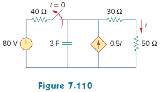
Chapter 7, Problem 43P
Consider the circuit in Fig. 7.110. Find i(t) for t < 0 and t > 0.
Expert Solution & Answer

Trending nowThis is a popular solution!

Students have asked these similar questions
8. Write down the expression of the follow circuits then try to simplified in possible:
D
(8)
(b)
DDD-
(c)
(d)
E.
G
(c)
(f)
Explain the duality theorem with example.
Digital electronics
Construct/Draw the Moore-type circuit
Chapter 7 Solutions
Fundamentals of Electric Circuits
Ch. 7.2 - Refer to the circuit in Fig. 7.7. Let vC (0) = 60...Ch. 7.2 - If the switch in Fig. 7.10 opens at t = 0, find...Ch. 7.3 - Find i and vx in the circuit of Fig. 7.15. Let...Ch. 7.3 - For the circuit in Fig. 7.18, find i(t) for t 0....Ch. 7.3 - Determine i, io, and vo for all t in the circuit...Ch. 7.4 - Express the current pulse in Fig. 7.33 in terms of...Ch. 7.4 - Refer to Fig. 7.39. Express i(t) in terms of...Ch. 7.4 - If h t = 0, t0 4, 0t2 3t8, 2t6 0, t6 express h(t)...Ch. 7.4 - Practice Problem 7.9 Evaluate the following...Ch. 7.5 - Find v(t) for t 0 in the circuit of Fig. 7.44....
Ch. 7.5 - The switch in Fig. 7.47 is closed at t = 0. Find...Ch. 7.6 - The switch in Fig. 7.52 has been closed for a long...Ch. 7.6 - Switch S1 in Fig. 7.54 is closed at t = 0, and...Ch. 7.7 - For the op amp circuit in Fig. 7.56, find vo for t...Ch. 7.7 - Find v(t) and vo(t) in the op amp circuit of Fig....Ch. 7.7 - Obtain the step response vo(t) for the circuit in...Ch. 7.8 - For the circuit in Fig. 7.66, use Pspice to find...Ch. 7.8 - The switch in Fig. 7.71 was open for a long time...Ch. 7.9 - The RC circuit in Fig. 7.74 is designed to operate...Ch. 7.9 - The flash unit of a camera has a 2-mF capacitor...Ch. 7.9 - A relay has a resistance of 200 and an inductance...Ch. 7.9 - Prob. 22PPCh. 7 - An RC circuit has R = 2 and C = 4 F. The time...Ch. 7 - The time constant for an RL circuit with R = 2 ...Ch. 7 - A capacitor in an RC circuit with R = 2 and C = 4...Ch. 7 - An RL circuit has R = 2 and L = 4 H. The time...Ch. 7 - In the circuit of Fig. 7.79, the capacitor voltage...Ch. 7 - Figure 7.79 For Review Questions 7.5 and 7.6....Ch. 7 - For the circuit in Fig. 7.80, the inductor current...Ch. 7 - Figure 7.80 For Review Questions 7.7 and 7.8....Ch. 7 - If vs changes from 2 V to 4 V at t = 0, we may...Ch. 7 - The pulse in Fig. 7.116(a) can be expressed in...Ch. 7 - In the circuit shown in Fig. 7.81...Ch. 7 - Find the time constant for the RC circuit in Fig....Ch. 7 - Determine the time constant for the circuit in...Ch. 7 - The switch in Fig. 7.84 has been in position A for...Ch. 7 - Using Fig. 7.85, design a problem to help other...Ch. 7 - The switch in Fig. 7.86 has been closed for a long...Ch. 7 - Assuming that the switch in Fig. 7.87 has been in...Ch. 7 - For the circuit in Fig. 7.88, if...Ch. 7 - The switch in Fig. 7.89 opens at t = 0. Find vo...Ch. 7 - For the circuit in Fig. 7.90, find vo(t) for t 0....Ch. 7 - For the circuit in Fig. 7.91, find io for t 0....Ch. 7 - Using Fig. 7.92, design a problem to help other...Ch. 7 - In the circuit of Fig. 7.93,...Ch. 7 - Calculate the time constant of the circuit in Fig....Ch. 7 - Find the time constant for each of the circuits in...Ch. 7 - Determine the time constant for each of the...Ch. 7 - Consider the circuit of Fig. 7.97. Find vo(t) if...Ch. 7 - For the circuit in Fig. 7.98, determine vo(t) when...Ch. 7 - In the circuit of Fig. 7.99, find i(t) for t 0 if...Ch. 7 - For the circuit in Fig. 7.100, v = 90e50t V and i...Ch. 7 - In the circuit of Fig. 7.101, find the value of R...Ch. 7 - Find i(t) and v(t) for t 0 in the circuit of Fig....Ch. 7 - Consider the circuit in Fig. 7.103. Given that...Ch. 7 - Express the following signals in terms of...Ch. 7 - Design a problem to help other students better...Ch. 7 - Express the signals in Fig. 7.104 in terms of...Ch. 7 - Express v(t) in Fig. 7.105 in terms of step...Ch. 7 - Sketch the waveform represented by i(t) = [r(t) ...Ch. 7 - Sketch the following functions: (a) x(t) = 10etu(t...Ch. 7 - Prob. 30PCh. 7 - Evaluate the following integrals: (a)e4t2(t2)dt...Ch. 7 - Prob. 32PCh. 7 - The voltage across a 10-mH inductor is 45(t 2)mV....Ch. 7 - Evaluate the following derivatives: (a) ddtut1ut+1...Ch. 7 - Find the solution to the following differential...Ch. 7 - Solve for v in the following differential...Ch. 7 - A circuit is described by 4dvdt+v=10 (a) What is...Ch. 7 - A circuit is described by didt+3i=2ut Find i(t)...Ch. 7 - Calculate the capacitor voltage for t 0 and t 0...Ch. 7 - Find the capacitor voltage for t 0 and t 0 for...Ch. 7 - Using Fig. 7.108, design a problem to help other...Ch. 7 - (a) If the switch in Fig. 7.109 has been open for...Ch. 7 - Consider the circuit in Fig. 7.110. Find i(t) for...Ch. 7 - The switch in Fig. 7.111 has been in position a...Ch. 7 - Find vo in the circuit of Fig. 7.112 when vs =...Ch. 7 - Prob. 46PCh. 7 - Determine v(t) for t 0 in the circuit of Fig....Ch. 7 - Find v(t) and i(t) in the circuit of Fig. 7.115....Ch. 7 - If the waveform in Fig. 7.116(a) is applied to the...Ch. 7 - In the circuit of Fig. 7.117, find ix for t 0....Ch. 7 - Rather than applying the shortcut technique used...Ch. 7 - Using Fig. 7.118, design a problem to help other...Ch. 7 - Determine the inductor current i(t) for both t 0...Ch. 7 - Obtain the inductor current for both t 0 and t 0...Ch. 7 - Find v(t) for t 0 and t 0 in the circuit of Fig....Ch. 7 - Prob. 56PCh. 7 - Prob. 57PCh. 7 - Rework Prob. 7.17 if i(0) = 10 A and v(t) = 20u(t)...Ch. 7 - Determine the step response vo(t) to is = 6u(t) A...Ch. 7 - Find v(t) for t 0 in the circuit of Fig. 7.125 if...Ch. 7 - In the circuit in Fig. 7.126, is changes from 5 A...Ch. 7 - For the circuit in Fig. 7.127, calculate i(t) if...Ch. 7 - Obtain v(t) and i(t) in the circuit of Fig. 7.128....Ch. 7 - Determine the value of iL(t) and the total energy...Ch. 7 - If the input pulse in Fig. 7.130(a) is applied to...Ch. 7 - Using Fig. 7.131, design a problem to help other...Ch. 7 - If v(0) = 10 V, find vo(t) for t 0 in the op amp...Ch. 7 - Prob. 68PCh. 7 - For the op amp circuit in Fig. 7.134, find vo(t)...Ch. 7 - Determine vo for t 0 when vs = 20 mV in the op...Ch. 7 - For the op amp circuit in Fig. 7.136, suppose vs =...Ch. 7 - Find io in the op amp circuit in Fig. 7.137....Ch. 7 - For the op amp circuit of Fig. 7.138, let R1 = 10...Ch. 7 - Determine vo(t) for t 0 in the circuit of Fig....Ch. 7 - In the circuit of Fig. 7.140, find vo and io,...Ch. 7 - Repeat Prob. 7.49 using PSpice or MultiSim. If the...Ch. 7 - The switch in Fig. 7.141 opens at t = 0. Use...Ch. 7 - The switch in Fig. 7.142 moves from position a to...Ch. 7 - In the circuit of Fig. 7.143, determine io(t)....Ch. 7 - In the circuit of Fig. 7.144, find the value of io...Ch. 7 - Repeat Prob. 7.65 using PSpice or MultiSim. If the...Ch. 7 - In designing a signal-switching circuit, it was...Ch. 7 - Prob. 83PCh. 7 - A capacitor with a value of 10 mF has a leakage...Ch. 7 - A simple relaxation oscillator circuit is shown in...Ch. 7 - Figure 7.146 shows a circuit for setting the...Ch. 7 - A 120-V dc generator energizes a motor whose coil...Ch. 7 - The circuit in Fig. 7.148(a) can be designed as an...Ch. 7 - An RL circuit may be used as a differentiator if...Ch. 7 - An attenuator probe employed with oscilloscopes...Ch. 7 - The circuit in Fig. 7.150 is used by a biology...Ch. 7 - To move a spot of a cathode-ray tube across the...
Knowledge Booster


Learn more about
Need a deep-dive on the concept behind this application? Look no further. Learn more about this topic, electrical-engineering and related others by exploring similar questions and additional content below.Similar questions
- Question 7.14. Please do by hand and use first order RL responsearrow_forwardAn independent voltage source is characterized by a terminal voltage which is completely independent of the current through it. Select one: True Falsearrow_forwardA sequential circuit with two FFs A & B , two inputs (XY) , and output Z has a state table given below, derive the next state equivalent of b(t+1)arrow_forward
- In the circuit shown in Fig. E7.3, the switch opens at t = 0. Find i1(t) for t > 0.arrow_forwardUsing the step-by-step method, find the value of the output current, io(t), just before the switch closes (at t=0-) for the network in Fig. P7.81. Given lç, 11 mA, R1 = 3 kQ, R2 = 6 kQ, R3 = 6 k0, and R4 = 7 KQ. 1 Is mA R1 ΚΩ Figure P7.81 R3 ΚΩ R2K t = 0 Los i,(1) 2 mH SR4K! Notes on entering solution: • Enter your solution in milliAmps(mA) • Enter your solution to the nearest tenth of a mA . Do not include units in your answer .ex. 5mA is entered as 5.0 2iAarrow_forwardFind the self induced emfarrow_forward
- Logical expression to canonical POS for the following: H(a,b,c)=b’arrow_forwardAn LTI system is considered.The response of the system to x1(t) is y1(t). Then find and sketch the response of the system to x2(t) and x3(t).arrow_forwardThe switch in the circuit below opens at t=0 after being kept in the closed position for a long time. Accordingly, which of the following is the value of di(0+)/dt?arrow_forward
- (c) Find the expression for iz(1) for t> 0 s. UTM The switch in the circuit of switch opened. UTM (b) Find the expression for ve(t) and sketch ve(t) for t> 0. Att=0 s, the 3 UTM O 5 UTM S UTM UTM & UTM & UTM 5 UTM 6 ko & UTM UTM 2 kn uF 4 k2 M 5 UTM t=0 S UTM &UTM UTM ww 5 UTM UTM Q.2 The switch in Figure Q.2 has been in position 4' for a long time. At t = 0 s t 24 V 4 k2 4 k2 S UTM position 'B'. swit S UTM UTM & UTM & UTM TM 8 UTM S UTM &UTM & UTM & UTM 5 UTM 8 UTM UTM 8 UTM B. UTM 5 UTM UTM & UTM 10n - UTAUTM/ 5 V 10 2 SM & UTM 20 mH Figure Q.2arrow_forwardQi Find Fcwl for the fullowing fuaction using differentiation property 7. 12arrow_forward8.7 MECT361 Mechatronics Components and Instrumentation 8.7. Given a 12-bit A/D converter operating over a voltage range from - 5 V to 5 V, how much does the input voltage have to change, in general, in order to be detectable? PLEASE GIVE ME THE REFRENCE I Will get zero if you didn't put the refrencearrow_forward
arrow_back_ios
SEE MORE QUESTIONS
arrow_forward_ios
Recommended textbooks for you
 Introductory Circuit Analysis (13th Edition)Electrical EngineeringISBN:9780133923605Author:Robert L. BoylestadPublisher:PEARSON
 Delmar's Standard Textbook Of ElectricityElectrical EngineeringISBN:9781337900348Author:Stephen L. HermanPublisher:Cengage Learning
 Programmable Logic ControllersElectrical EngineeringISBN:9780073373843Author:Frank D. PetruzellaPublisher:McGraw-Hill Education
 Fundamentals of Electric CircuitsElectrical EngineeringISBN:9780078028229Author:Charles K Alexander, Matthew SadikuPublisher:McGraw-Hill Education
 Electric Circuits. (11th Edition)Electrical EngineeringISBN:9780134746968Author:James W. Nilsson, Susan RiedelPublisher:PEARSON
 Engineering ElectromagneticsElectrical EngineeringISBN:9780078028151Author:Hayt, William H. (william Hart), Jr, BUCK, John A.Publisher:Mcgraw-hill Education,
Introductory Circuit Analysis (13th Edition)
Electrical Engineering
ISBN:9780133923605
Author:Robert L. Boylestad
Publisher:PEARSON
Delmar's Standard Textbook Of Electricity
Electrical Engineering
ISBN:9781337900348
Author:Stephen L. Herman
Publisher:Cengage Learning
Programmable Logic Controllers
Electrical Engineering
ISBN:9780073373843
Author:Frank D. Petruzella
Publisher:McGraw-Hill Education
Fundamentals of Electric Circuits
Electrical Engineering
ISBN:9780078028229
Author:Charles K Alexander, Matthew Sadiku
Publisher:McGraw-Hill Education
Electric Circuits. (11th Edition)
Electrical Engineering
ISBN:9780134746968
Author:James W. Nilsson, Susan Riedel
Publisher:PEARSON
Engineering Electromagnetics
Electrical Engineering
ISBN:9780078028151
Author:Hayt, William H. (william Hart), Jr, BUCK, John A.
Publisher:Mcgraw-hill Education,
ENA 9.2(1)(En)(Alex) Sinusoids & Phasors - Explanation with Example 9.1 ,9.2 & PP 9.2; Author: Electrical Engineering Academy;https://www.youtube.com/watch?v=vX_LLNl-ZpU;License: Standard YouTube License, CC-BY
Electrical Engineering: Ch 10 Alternating Voltages & Phasors (8 of 82) What is a Phasor?; Author: Michel van Biezen;https://www.youtube.com/watch?v=2I1tF3ixNg0;License: Standard Youtube License