
Fundamentals of Electric Circuits
6th Edition
ISBN: 9780078028229
Author: Charles K Alexander, Matthew Sadiku
Publisher: McGraw-Hill Education
expand_more
expand_more
format_list_bulleted
Concept explainers
Videos
Textbook Question
Chapter 5, Problem 40P
Referring to the circuit shown in Fig. 5.77, determine Vo in terms of V1 and V2.
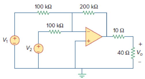
Figure 5.77
For Prob. 5.40.
Expert Solution & Answer
Want to see the full answer?
Check out a sample textbook solution
Students have asked these similar questions
5.2. Determine V out as a function of I (provided by a current source) and the resistor
values for each of the op amp circuits that follows. Assume ideal op amp behavior.
Vout
R1
(a) I
R2
R3
R4
R3
R1
(b) I
V.
out
R2
5.39 For the op amp circuit in Fig. 5.76, determine the
value of v2 in order to make v, = -16.5 V.
10 k2
50 k2
-3 V O
20 k2
V2 O
+
50 k2
5 V o
5.59 In the op amp circuit of Fig. 5.86, determine the
voltage gain v,/vg. Take R = 10 k2.
2R
4R
R
R
Vs
Chapter 5 Solutions
Fundamentals of Electric Circuits
Ch. 5.2 - If the same 741 op amp in Example 5.1 is used in...Ch. 5.3 - Repeat Example 5.1 using the ideal op amp model....Ch. 5.4 - Practice Problem 5.3 Figure 5.13 For Practice...Ch. 5.4 - Two kinds of current-to-voltage converters (also...Ch. 5.5 - Calculate vo in the circuit of Fig. 5.20. Answer:...Ch. 5.6 - Practice Problem 5.6 Find vo and io in the op amp...Ch. 5.7 - Design a difference amplifier with gain 7.5....Ch. 5.7 - Obtain io in the instrumentation amplifier circuit...Ch. 5.8 - Practice Problem 5.9 Figure 5.30 For Practice...Ch. 5.8 - If v1 = 5 V and v2 = 5 V, find vo in the op amp...
Ch. 5.9 - Rework Practice Prob. 5.1 using PSpice. If the...Ch. 5.10 - A three-bit DAC is shown in Fig. 5.37. (a)...Ch. 5.10 - Determine the value of the external gain-setting...Ch. 5 - The two input terminals of an op amp are labeled...Ch. 5 - For an ideal op amp, which of the following...Ch. 5 - For the circuit in Fig. 5.40, voltage vo is: (a)6...Ch. 5 - For the circuit in Fig. 5.40, current ix is:...Ch. 5 - If vs = 0 in the circuit of Fig. 5.41, current io...Ch. 5 - If vs = 8 mV in the circuit of Fig. 5.41, the...Ch. 5 - Refer to Fig. 5.41. If vs = 8 mV, voltage va is:...Ch. 5 - The power absorbed by the 4-k resistor in Fig....Ch. 5 - Which of these amplifiers is used in a...Ch. 5 - Difference amplifiers are used in (please check...Ch. 5 - The equivalent model of a certain op amp is shown...Ch. 5 - The open-loop gain of an op amp is 50,000....Ch. 5 - Determine the voltage input to the inverting...Ch. 5 - The output voltage of an op amp is 4 V when the...Ch. 5 - For the op amp circuit of Fig. 5.44, the op amp...Ch. 5 - Using the same parameters for the 741 op amp in...Ch. 5 - 5.7 The op amp in Fig. 5.46 has Ri = 100 k, Ro =...Ch. 5 - Obtain vo for each of the op amp circuits in Fig....Ch. 5 - Determine vo for each of the op amp circuits in...Ch. 5 - Prob. 10PCh. 5 - Using Fig. 5.50, design a problem to help other...Ch. 5 - Calculate the voltage ratio vo/vs for the op amp...Ch. 5 - Find vo and io in the circuit of Fig. 5.52. Figure...Ch. 5 - Determine the output voltage vo in the circuit of...Ch. 5 - (a)Determine the ratio vo/is in the op amp circuit...Ch. 5 - Using Fig. 5.55, design a problem to help students...Ch. 5 - Prob. 17PCh. 5 - For the circuit shown in Figure 5.57, solve for...Ch. 5 - Determine io in the circuit of Fig. 5.58. Figure...Ch. 5 - In the circuit of Fig. 5.59, calculate vo of vs =...Ch. 5 - Calculate vo in the op amp circuit of Fig. 5.60....Ch. 5 - Design an inverting amplifier with a gain of 15.Ch. 5 - For the op amp circuit in Fig. 5.61, find the...Ch. 5 - In the circuit shown in Fig. 5.62, find k in the...Ch. 5 - Calculate vo in the op amp circuit of Fig. 5.63....Ch. 5 - Using Fig. 5.64, design a problem to help other...Ch. 5 - Find vo in the op amp circuit of Fig. 5.65. Figure...Ch. 5 - Prob. 28PCh. 5 - Determine the voltage gain vo/vi of the op amp...Ch. 5 - In the circuit shown in Fig. 5.68, find ix and the...Ch. 5 - For the circuit in Fig. 5.69, find ix. Figure 5.69...Ch. 5 - Calculate ix and vo in the circuit of Fig. 5.70....Ch. 5 - Refer to the op amp circuit in Fig. 5.71....Ch. 5 - Given the op amp circuit shown in Fig. 5.72,...Ch. 5 - Design a noninverting amplifier with a gain of...Ch. 5 - For the circuit shown in Fig. 5.73, find the...Ch. 5 - Determine the output of the summing amplifier in...Ch. 5 - Using Fig. 5.75, design a problem to help other...Ch. 5 - For the op amp circuit in Fig. 5.76, determine the...Ch. 5 - Referring to the circuit shown in Fig. 5.77,...Ch. 5 - An averaging amplifier is a summer that provides...Ch. 5 - The feedback resistor of a three-input averaging...Ch. 5 - The feedback resistor of a five-input averaging...Ch. 5 - Show that the output voltage vo of the circuit in...Ch. 5 - Design an op amp circuit to perform the following...Ch. 5 - Using only two op amps, design a circuit to solve...Ch. 5 - The circuit in Fig. 5.79 is for a difference...Ch. 5 - The circuit in Fig. 5.80 is a differential...Ch. 5 - Design a difference amplifier to have a gain of 4...Ch. 5 - Design a circuit to amplify the difference between...Ch. 5 - Using two op amps, design a subtractor.Ch. 5 - Design an op amp circuit such that vo = 4v1 + 6v2 ...Ch. 5 - The ordinary difference amplifier for fixed-gain...Ch. 5 - Determine the voltage transfer ratio vovs in the...Ch. 5 - In a certain electronic device, a three-stage...Ch. 5 - Using Fig. 5.83, design a problem to help other...Ch. 5 - Find vo in the op amp circuit of Fig. 5.84.Ch. 5 - Calculate io in the op amp circuit of Fig. 5.85....Ch. 5 - In the op amp circuit of Fig. 5.86, determine the...Ch. 5 - Calculate vo/vi in the op amp circuit of Fig....Ch. 5 - Determine vo in the circuit of Fig. 5.88. Figure...Ch. 5 - Obtain the closed-loop voltage gain vo/vi of the...Ch. 5 - Determine the gain vovi of the circuit in Fig....Ch. 5 - For the op amp circuit shown in Fig. 5.91, find...Ch. 5 - Find vo in the op amp circuit of Fig. 5.92.Ch. 5 - For the circuit in Fig. 5.93, find vo.Ch. 5 - Obtain the output vo in the circuit of Fig. 5.94....Ch. 5 - Find vo in the circuit of Fig. 5.95, assuming that...Ch. 5 - Find vo in the circuit of Fig. 5.95, assuming that...Ch. 5 - Determine vo in the op amp circuit of Fig. 5.96.Ch. 5 - Determine vo in the op amp circuit of Fig. 5.97.Ch. 5 - Find the load voltage vL in the circuit of Fig....Ch. 5 - Determine the load voltage vL in the circuit of...Ch. 5 - Find io in the op amp circuit of Fig. 5.100....Ch. 5 - Rework Example 5.11 using the nonideal op amp...Ch. 5 - Solve Prob. 5.19 using PSpice or MultiSim and op...Ch. 5 - Solve Prob. 5.48 using PSpice or MultiSim and op...Ch. 5 - Use PSpice or MultiSim to obtain vo in the circuit...Ch. 5 - Determine vo in the op amp circuit of Fig. 5.102,...Ch. 5 - Use PSpice or MultiSim to solve Prob. 5.70....Ch. 5 - Use PSpice or MultiSim to verify the results in...Ch. 5 - Prob. 82PCh. 5 - Design a six-bit digital-to-analog converter. (a)...Ch. 5 - A four-bit R-2R ladder DAC is presented in Fig....Ch. 5 - In the op amp circuit of Fig. 5.104, find the...Ch. 5 - Design a voltage controlled ideal current source...Ch. 5 - Figure 5.105 displays a two-op-amp instrumentation...Ch. 5 - Figure 5.106 shows an instrumentation amplifier...Ch. 5 - Design a circuit that provides a relationship...Ch. 5 - The op amp circuit in Fig. 5.107 is a current...Ch. 5 - A noninverting current amplifier is portrayed in...Ch. 5 - Refer to the bridge amplifier shown in Fig. 5.109....Ch. 5 - A voltage-to-current converter is shown in Fig....
Knowledge Booster


Learn more about
Need a deep-dive on the concept behind this application? Look no further. Learn more about this topic, electrical-engineering and related others by exploring similar questions and additional content below.Similar questions
- Find v, and i, in the op amp circuit shown in Fig. 5.23. 20 k2 8 kn ww ww 10 kQ 6 kN 15 V ww 2 V 4 k2 12 V Figure 5.23 For Practice Prob. 5.6. wwarrow_forwardHW25 5.57 Find v, in the op amp circuit of Fig. 5.84. 50 ΚΩ 100 kΩ 100 kΩ ww 25 k2 V;1 o ww ww ww 100 k2 50 k2 50 k2arrow_forwardVD- R1 R2 A VOUT VIN VD+ R3 R4 Figure 5.27 Differential amplifier using op amp, arranged with dashed-line connections to measure CMRR of op amp.arrow_forward
- LMH_chapter3-part 1-homework [Protected View] PowerPoint ĐĂNG PHẠM HỒNG File Home Insert Design Transitions Animations Slide Show Review View Help Tell me what you want to do & Share 1 Chapter III HW15 AC Circuit Analysis Homework part 1 Reading: Chapter 05 Textbook: Fundamental of Electric Circuits Textbook 5.10 Find the gain v,/v, of the circuit in Fig. 5.49. 2 HW14 5.7 The op amp in Fig 5.46 has R, - 100 k, R, - 100 2, 4- 100,000. Find dhe dillerential volage e, and the output voltage v. 37 k2 10 k 100 A 20 kΩ I mv :) 3. HW15 5.10 Find the gain r/v, of the circait in Fig. 5.49. 10 k2 37 ko 20 k2 4 HW16 5.13 Find u, andi, in the circuit of Fig. 5.52. 3 1v O 100 k2 E90 ka 10 k2 50 kaarrow_forwardR4 As R3 R Figure 5.26 Instrumentation amplifier; for Example 5.8. Since the op amps Aj and A2 draw no current, current i flows through the three resistors as though they were in series. Hence, Vol - vo2 = i (R3 + R4 + R3) =i (2R3 + R4) (5.8.2) But Va - U i = RA and v, = v1, vh = v2. Therefore, vi - v2 i = R4 (5.8.3) Inserting Eqs. (5.8.2) and (5.8.3) into Eq. (5.8.1) gives R2 Vo = 2R3 + (v2 – v1) R4 as required. We will discuss the instrumentation amplifier in detail in Section 5.10. ROBLEM 5.8 Obtain i, in the instrumentation amplifier circuit of Fig. 5.27. 8.00 V o 40 ka ww- 20 k2 ww- -ww 20 k2 8.01 V o 40 k2 10 kn Figure 5.27 Instrumentation amplifier; for Practice Prob. 5.8. Answer: 2 µA. CНАРТER 5 Operational Amplifiers 181 DED OP AMP CIRCUITS amp circuits are modules or building blocks for designing s. It is often necessary in practical applications to connect in cascade (i.e., head to tail) to achieve a large overall 1, two circuits are cascaded when they are connected in ind…arrow_forward5.39 For the op amp circuit in Fig. 5.74, determine the value of v2 in order to make vo = -16.5 V. 10 ΚΩ +2VO www 20 ΚΩ 22 OM 50 ΚΩ -1 V O www Ans: V2 = 3 volts 50 ΚΩ www Voarrow_forward
- HW26 5.70 Determine v, in the op amp circuit of Fig. 5.96. 30 ΚΩ 40 kQ ww ww 10 ΚΩ A 20 k2 ww- 1V 60 kQ 10 k2 ww 10 k2 2 V 20 Ω w 10 k2 ww В 3V 10 k2 4V 14 wwHarrow_forwardPractice (4.2): Repeat Example 5.1 using the ideal op amp model. Ans: -2, 200 uA. 20 k2 10 k2 1 741 Vs Fig. (4.6) ahme91.d |Earrow_forward5.6 Design a flyback PWM converter to meet the following specifications: V₁ = 270 Vdc ±10%, Vo = 28 V, Io = 0.2-2 A, and V₁/Vo ≤ 1%. Find n, Lm, C, and n.arrow_forward
- Problem (1): Section 5.3 Ideal Op Amp 5.8 Obtain v, for each of the op amp circuits in Fig. 5.47. 1 mA Figure 5.47 ForProb. 5.8. (a) 2 ΚΩ wwww +1. 9+19 2 V 1 V 10 ΚΩ www 2 ΚΩ Voarrow_forward+ des y S, ng lues of Section 5.7 Difference Amplifier 5.47 The circuit in Fig. 5.79 is for a difference amplifier. Find v, vo given that v₁ = 1 V and v₂ = 2 V. V₁ + V2 PR 2 ΚΩ ww +1 Figure 5.79 For Prob. 5.47. 2 ΚΩ ww S www C 20 ΚΩ 30 ΚΩ ww 5.48 The circuit in Fig. 5.80 is a differential amplifier driven by a bridge. Find vo. + I + o Vo 10arrow_forwardThe op amp in Fig. 5.46 has R;= 100 k2, R,-100 Ω, Α voltage va and the output voltage v.. 5.7 100,000. Find the differential Vd 10 k2 100 k2 + + 1 mVarrow_forward
arrow_back_ios
SEE MORE QUESTIONS
arrow_forward_ios
Recommended textbooks for you
 Introductory Circuit Analysis (13th Edition)Electrical EngineeringISBN:9780133923605Author:Robert L. BoylestadPublisher:PEARSON
 Delmar's Standard Textbook Of ElectricityElectrical EngineeringISBN:9781337900348Author:Stephen L. HermanPublisher:Cengage Learning
 Programmable Logic ControllersElectrical EngineeringISBN:9780073373843Author:Frank D. PetruzellaPublisher:McGraw-Hill Education
 Fundamentals of Electric CircuitsElectrical EngineeringISBN:9780078028229Author:Charles K Alexander, Matthew SadikuPublisher:McGraw-Hill Education
 Electric Circuits. (11th Edition)Electrical EngineeringISBN:9780134746968Author:James W. Nilsson, Susan RiedelPublisher:PEARSON
 Engineering ElectromagneticsElectrical EngineeringISBN:9780078028151Author:Hayt, William H. (william Hart), Jr, BUCK, John A.Publisher:Mcgraw-hill Education,
Introductory Circuit Analysis (13th Edition)
Electrical Engineering
ISBN:9780133923605
Author:Robert L. Boylestad
Publisher:PEARSON
Delmar's Standard Textbook Of Electricity
Electrical Engineering
ISBN:9781337900348
Author:Stephen L. Herman
Publisher:Cengage Learning
Programmable Logic Controllers
Electrical Engineering
ISBN:9780073373843
Author:Frank D. Petruzella
Publisher:McGraw-Hill Education
Fundamentals of Electric Circuits
Electrical Engineering
ISBN:9780078028229
Author:Charles K Alexander, Matthew Sadiku
Publisher:McGraw-Hill Education
Electric Circuits. (11th Edition)
Electrical Engineering
ISBN:9780134746968
Author:James W. Nilsson, Susan Riedel
Publisher:PEARSON
Engineering Electromagnetics
Electrical Engineering
ISBN:9780078028151
Author:Hayt, William H. (william Hart), Jr, BUCK, John A.
Publisher:Mcgraw-hill Education,
Z Parameters - Impedance Parameters; Author: Electrical Engineering Authority;https://www.youtube.com/watch?v=qoD4AoNmySA;License: Standard Youtube License