
Concept explainers
Videos
In the circuit shown in Fig. 5.62, find k in the voltage transfer function vo = kvs.
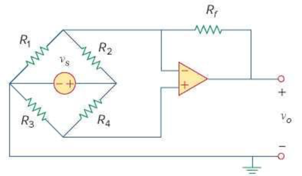
Figure 5.62
For Prob. 5.24.
Derive the expression for k in the voltage transfer function
Answer to Problem 24P
The expression for k is
Explanation of Solution
Given data:
Refer to Figure 5.62 in the textbook for the given op amp circuit.
Calculation:
Modify the Figure 5.62 by indicating the node voltages
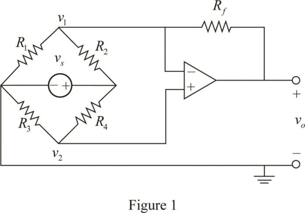
From the properties of ideal op amp, consider that the voltage across the two input terminals of op amp is equal to zero.
Apply Kirchhoff's current law to the node
Apply Kirchhoff's current law to the node
Simplify the equation as follows.
Substitute equation (1) in (3).
Substitute equation (4) in (2).
Consider the expression for the voltage transfer function.
Compare equations (5) and (6).
Conclusion:
Thus, the expression for k is
Want to see more full solutions like this?
Chapter 5 Solutions
Fundamentals of Electric Circuits


- A "RL circuit" with 18ohm resistor and a 0.30 Henry inductor. If it has an initial current of 1 amp, what would the current will be after 0.017 sec?arrow_forwardI already asked this once and it was answered incorrectly. Solve Vx using kcl and/or kvl and find it symbolically. The final answer should be -2A0R. Redraw the circuit as needed and explain the redrawn circuit as well. Note: it's an ideal op amp.arrow_forwardDesign inegreator circuit without OP-AMP in multisim. (Take R=10K ohm,,C=10 microfarad)arrow_forward
- *5.88 Figure 5.106 shows an instrumentation amplifier driven by a bridge. Obtain the gain vo/v; of the amplifier. 25 k2 500 k2 20 kQ 30 k2 10 k2 + 40 kΩ 80 kQ 2 kΩ 10 k2 25 k2 500 kQ Figure 5.106 For Prob. 5.88.arrow_forwardVD- R1 R2 A VOUT VIN VD+ R3 R4 Figure 5.27 Differential amplifier using op amp, arranged with dashed-line connections to measure CMRR of op amp.arrow_forwardDesign an inverting op amp circuit with 6.5 gainarrow_forward
- The Junction Gate Field Effect Transistor is one of the simplest types of field-effect transistor. It is a three-terminal semiconductor device .One of its function is, it serve as an amplifier. As an Engineer you are to design a single stage JFET Amplifier. Explain in your own words this circuit operates, identifying each component in your design circuit and state their functionsarrow_forwardAn 8-bit D/A converter has a step size of 10mV. Determine the full scale and percent resolution of the converter.arrow_forwardBASIC ELECTRONICS Given Idss = 12mA and Vp= -4V Sketch the drain and transconductance curve for VGS = +2V, +1V, 0V -1V, -2V, -3V and -4Varrow_forward
- For the following circuits, determine and sketch the output waveforms given the input waveforms shown. Provide calculations and/or sufficient explanations to support your drawings. a) Circuit A: 6V Ideal - 20V + V V, R Vo -20V b) Circuit B: C 20V Ideal R 8V V -20V +arrow_forwardDesign an inverting circuit using a single operational amplifier that will produce the output vo = –4v1 – 6v2.arrow_forwardAn op amp has a GBP of 106 . A 0.3 μV sinusoidal signal at 5 KHz is required to beamplified to 5 V. Calculate the gains and draw the schematic circuit to achieve this.arrow_forward
 Introductory Circuit Analysis (13th Edition)Electrical EngineeringISBN:9780133923605Author:Robert L. BoylestadPublisher:PEARSON
 Delmar's Standard Textbook Of ElectricityElectrical EngineeringISBN:9781337900348Author:Stephen L. HermanPublisher:Cengage Learning
 Programmable Logic ControllersElectrical EngineeringISBN:9780073373843Author:Frank D. PetruzellaPublisher:McGraw-Hill Education
 Fundamentals of Electric CircuitsElectrical EngineeringISBN:9780078028229Author:Charles K Alexander, Matthew SadikuPublisher:McGraw-Hill Education
 Electric Circuits. (11th Edition)Electrical EngineeringISBN:9780134746968Author:James W. Nilsson, Susan RiedelPublisher:PEARSON
 Engineering ElectromagneticsElectrical EngineeringISBN:9780078028151Author:Hayt, William H. (william Hart), Jr, BUCK, John A.Publisher:Mcgraw-hill Education,