
Videos
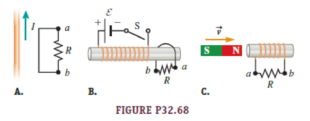
Each of the three situations in Figure P32.68 shows a resistor in a circuit in which currents are induced. Using Lenz’s law, determine whether the current in each situation is from a to b or from b to a. a. If the current I in the wire in Figure P32.68A is increased from zero to I, what is the direction of the current induced across the resistor R? b. The switch in Figure P32.68B is initially closed and is thrown open at t = 0. What is the direction of the current induced across the resistor R immediately afterward? c. A bar magnet is brought close to the circuit shown in Figure P32.68C. What is the direction of the current induced across the resistor R?

Trending nowThis is a popular solution!

Chapter 32 Solutions
Physics for Scientists and Engineers: Foundations and Connections


- A loop of wire sits in an external magnetic field as shown (in other words, the field shown in the picture is NOT a field created by the loop). The loop has a radius of 2.8 m. If the external magnetic field changes from 5.5 T to 11 T in 6.1 s, what is the magnitude of the induced emf in the loop? a. 2.22×101 V b. 2.22×101 V c. 1.59×101 V d. 4.44×101 V e. 7.07 Varrow_forwardA2.40 cm x 2.40 cm square loop of wire with resistance 1.30x10⁻² Q has one edge parallel to a long straight wire. The near edge of the loop is 1.20 cm from the wire. The current in the wire is increasing at the rate of 120 A/s . Part A What is the current in the loop? μΑ Submit Request Answerarrow_forwardA TMS (transcranial magnetic stimulation) device creates very rapidly changing magnetic fields. The field near a typical pulsed-field machine rises from 0 T to 2.5 T in 200 μs. Suppose a technician holds his hand near the device so that the axis of his 2.0-cm-diameter wedding band is parallel to the field.a. What emf is induced in the ring as the field changes?b. If the band is made of a gold alloy with resistivity 6.2 x 10⁻⁸ Ω • m and has a cross-section area of 4.0 mm2, what is the induced current?arrow_forward
- A2.10 cm x 2.10 cm square loop of wire with resistance 1.00×10⁻² has one edge parallel to a long straight wire. The near edge of the loop is 1.10 cm from the wire. The current in the wire is increasing at the rate of 120 A/s.arrow_forwardA square coil of wire has 10 turns and an area of 20 cm^2. The square coil is located in a variable magnetic field whose behavior is shown on the graph. The magnetic field is directed at an angle of 45° relative to the normal to the plane of the square coil. a. What is the average emf induced in the coil in the time interval from t=7.50 s to 10.0 s? b. If the wire has a resistance of 0.75 Ω determine the induced current for the interval from part (a)?arrow_forward1. A 1.50 V battery is connected in series with a capacitor and a 275Ω resistor. a. What is the charge and the voltage across the capacitor immediately after the switch is closed? b. At steady state, what will be the potential across the capacitor? 2. A loop of wire in the form of a square 1.50 m on each side, its plane makes an angle of 40.0° with a uniform magnetic field of 0.95 T. What is the magnetic flux through the loop?arrow_forward
- 30. A short wire runs along an x axis from x = a to x = -a (Figure P30.30). At t = 0, there is a small sphere carry- ing charge +9o at x = a and a small sphere carrying charge -9o at x = -a. As the spheres discharge and a current is established in the wire, show that, for t>0, the generalized form of Ampère's law (Eq. 30.13) and the Biot-Savart law (Eq. 28.12) give the same result for the magnitude of the mag- netic field a distance b up the y axis. (Hint: Obtain the elec- tric flux through a circular disk in the yz plane, centered at the origin. Because the electric field is not constant over the surface of the disk, you must divide the disk into a nested set of rings of various radii and integrate. A representative ring should have radius r and radial extent dr.) •.. Figure P30.30 b -90arrow_forwardA The diagram shows a rectangular loop of wire moving away (in the direction of the blue arrow) from a long, straight wire carrying a constant current, 1, in the direction of the red arrow. Which of the following describes the induced current in the resistor in the rectangular loop? O The induced current in the resistor is directed from B to A. O The induced current in the resistor is directed from A to B. O There is no induced current flowing through the resistor.arrow_forwardTwo wires are parallel, with one directly above the other, 9 cm apart. Each wire has aweight per unit length of 1.00 x 10⁻⁴ N/m. Assume the wires carry currents that are equalin magnitude. a. Find the current in the wires if the upper wire is floating (balanced) above the lowerwire b.What can you tell about the directions of the current in the two wires?arrow_forward
- A square, 44.0-turn coil that is 13.0 cm on a side with a resistance of 0.900 2 is placed between the poles of a large electromagnet. The electromagnet produces a constant, uniform magnetic field of 0.400 T directed into the screen. As suggested by the figure, the field drops sharply to zero at the edges of the magnet. The coil moves to the right at a constant velocity of 3.10 cm/s. N-turn coil B into the screen Varrow_forwardSuppose a magnetic field B(t) oscillates with frequency w. A circular loop of copper lies perpendicular to the magnetic field. The radius of the circular loop is r. a. Write down an expression for the magnetic field as a function of time. Determine the induced emf & in the loop of wire and use this to calculate the current generated in the loop as a function of time. b. What is the power dissipation in the wire as a function to time? Make a sketch of this function. What is the average power Pave dissipation in the wire? Hint: what is the average value of the function you sketched? C. Recall that power is a rate of energy transfer, and that power dissipated by a resistor leads to a change in the thermal energy of the material (in this case the copper wire). We can relate a change in thermal energy to a change in temperature by AT where M is the total mass and c ΔΕth Mc is the specific heat capacity of the material (see page 526 for details). Find an expression for a dT - differential…arrow_forwardThe drawing shows a straight wire carrying a current I. Above the wire is a rectangular loop that contains a resistor R. If the current I is decreasing in time, what is the direction of the induced current through the resistor R — left-to-right or right-to-left? If the induced current goes from left to right through the resistor, type the letters "LTR" in the box below. If the current goes from right to left through the resistor, type the letters "RTL" in the box.arrow_forward
 Physics for Scientists and Engineers: Foundations...PhysicsISBN:9781133939146Author:Katz, Debora M.Publisher:Cengage Learning