
Loose Leaf for Engineering Circuit Analysis Format: Loose-leaf
9th Edition
ISBN: 9781259989452
Author: Hayt
Publisher: Mcgraw Hill Publishers
expand_more
expand_more
format_list_bulleted
Concept explainers
Videos
Textbook Question
Chapter 3, Problem 62E
Delete the leftmost 10 Ω resistor in the circuit of Fig. 3.98. and compute (a) the current flowing into the left-hand terminal of the 40 Ω resistor; (b) the power supplied by the 20 V source; (c) the power dissipated by the 50 Ω resistor.
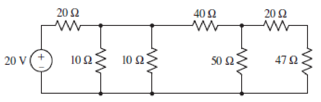
FIGURE 3.98
Expert Solution & Answer
Want to see the full answer?
Check out a sample textbook solution
Students have asked these similar questions
Q3)
A) Find RAB for the circuit shown in Figure 3.
A O
4 N
50
Figure 3
Q3: Find the equivalent circuit between the terminals a and b, then find the
value of Rithat can be place between the terminals to deliver the maximum
power from the source
Hint: use RL values smaller, equal, greater than RTh, then decide which one
you have to pick!
30 Ω
a
360 V
150 Ωξ
RL
b
3. Draw clearly the circuits given in Figure 3 (a and b) on the paper provided for your use in the LMS.
Rs
R,
R2
R4
R3
E,
R
Ra
Rs
V (t
(a)
(b)
Figure 3
Chapter 3 Solutions
Loose Leaf for Engineering Circuit Analysis Format: Loose-leaf
Ch. 3.2 - 3.1 (a) Count the number of branches and nodes in...Ch. 3.3 - Determine ix and vx in the circuit of Fig. 3.7....Ch. 3.3 - For the circuit of Fig. 3.9, if vR1=1V, determine...Ch. 3.3 - Determine vx in the circuit of Fig. 3.11.Ch. 3.4 - In the circuit of Fig. 3.12b, vs1 = 120 V, vs2 =...Ch. 3.4 - 3.6 In the circuit of Fig. 3.14, find the power...Ch. 3.5 - Determine v in the circuit of Fig. 3.16.Ch. 3.5 - For the single-node-pair circuit of Fig. 3.18,...Ch. 3.6 - Determine the current i in the circuit of Fig....Ch. 3.6 - Determine the voltage v in the circuit of Fig....
Ch. 3.6 - Determine whether the circuit of Fig. 3.25...Ch. 3.7 - 3.12 Determine a single-value equivalent...Ch. 3.7 - 3.13 Determine i in the circuit of Fig. 3.29....Ch. 3.7 - Determine v in the circuit of Fig. 3.31 by first...Ch. 3.7 - 3.15 For the circuit of Fig. 3.33, calculate the...Ch. 3.8 - 3.16 Use voltage division to determine vx in the...Ch. 3.8 - In the circuit of Fig. 3.40, use resistance...Ch. 3 - Referring to the circuit depicted in Fig. 3.45,...Ch. 3 - Referring to the circuit depicted in Fig. 3.46,...Ch. 3 - For the circuit of Fig. 3.47: (a) Count the number...Ch. 3 - For the circuit of Fig. 3.47: (a) Count the number...Ch. 3 - Refer to the circuit of Fig. 3.48, and answer the...Ch. 3 - A local restaurant has a neon sign constructed...Ch. 3 - Referring to the single-node diagram of Fig. 3.50,...Ch. 3 - Determine the current labeled I in each of the...Ch. 3 - In the circuit shown in Fig. 3.52, the resistor...Ch. 3 - The circuit of Fig. 3.53 represents a system...Ch. 3 - In the circuit depicted in Fig. 3.54, ix is...Ch. 3 - For the circuit of Fig. 3.55 (which employs a...Ch. 3 - Determine the current labeled I3 in the circuit of...Ch. 3 - Study the circuit depicted in Fig. 3.57, and...Ch. 3 - Prob. 15ECh. 3 - For the circuit of Fig. 3.58: (a) Determine the...Ch. 3 - For each of the circuits in Fig. 3.59, determine...Ch. 3 - Use KVL to obtain a numerical value for the...Ch. 3 - Prob. 19ECh. 3 - In the circuit of Fig. 3.55, calculate the voltage...Ch. 3 - Determine the value of vx as labeled in the...Ch. 3 - Consider the simple circuit shown in Fig. 3.63....Ch. 3 - (a) Determine a numerical value for each current...Ch. 3 - The circuit shown in Fig. 3.65 includes a device...Ch. 3 - The circuit of Fig. 3.12b is constructed with the...Ch. 3 - Obtain a numerical value for the power absorbed by...Ch. 3 - Compute the power absorbed by each element of the...Ch. 3 - Compute the power absorbed by each element in the...Ch. 3 - Kirchhoffs laws apply whether or not Ohms law...Ch. 3 - Referring to the circuit of Fig. 3.70, (a)...Ch. 3 - Determine a value for the voltage v as labeled in...Ch. 3 - Referring to the circuit depicted in Fig. 3.72,...Ch. 3 - Determine the voltage v as labeled in Fig. 3.73,...Ch. 3 - Although drawn so that it may not appear obvious...Ch. 3 - Determine the numerical value for veq in Fig....Ch. 3 - Determine the numerical value for ieq in Fig....Ch. 3 - For the circuit presented in Fig. 3.76. determine...Ch. 3 - Determine the value of v1 required to obtain a...Ch. 3 - (a) For the circuit of Fig. 3.78, determine the...Ch. 3 - What value of IS in the circuit of Fig. 3.79 will...Ch. 3 - (a) Determine the values for IX and VY in the...Ch. 3 - Determine the equivalent resistance of each of the...Ch. 3 - For each network depicted in Fig. 3.82, determine...Ch. 3 - (a) Simplify the circuit of Fig. 3.83 as much as...Ch. 3 - (a) Simplify the circuit of Fig. 3.84, using...Ch. 3 - Making appropriate use of resistor combination...Ch. 3 - Calculate the voltage labeled vx in the circuit of...Ch. 3 - Determine the power absorbed by the 15 resistor...Ch. 3 - Calculate the equivalent resistance Req of the...Ch. 3 - Show how to combine four 100 resistors to obtain...Ch. 3 - Prob. 51ECh. 3 - Prob. 52ECh. 3 - Prob. 53ECh. 3 - Prob. 54ECh. 3 - Prob. 55ECh. 3 - Prob. 56ECh. 3 - Prob. 57ECh. 3 - Prob. 58ECh. 3 - Prob. 59ECh. 3 - Prob. 60ECh. 3 - With regard to the circuit shown in Fig. 3.98,...Ch. 3 - Delete the leftmost 10 resistor in the circuit of...Ch. 3 - Consider the seven-element circuit depicted in...
Knowledge Booster


Learn more about
Need a deep-dive on the concept behind this application? Look no further. Learn more about this topic, electrical-engineering and related others by exploring similar questions and additional content below.Similar questions
- 3.32. While constructing a full-wave rectifier, a student mistakenly has swapped the termi- nals of D3 as depicted in Fig. 3.82. Explain what happens. D2. D3 * Vout + Vin RL DA Figure 3.82arrow_forward1. For the circuit shown below, find: i) the total current ii) the current in the 8 Q resistor iii) the voltage drop across the 3N resistorarrow_forward3.Complete the Table of Values for this circuit: 220 2 100 2 ww R4 Rī 470 2 R, 18 V 1302 270 2 R2 Rs R1 R2 R3 R4 R5 Total R 2202 1302 4702 1002 2702 Ω V 18 V I mA P Warrow_forward
- Employ superposition to determine the individual contribution from each independent source to the voltage v as labeled in the circuit shown in Figure 3. 10 6 A 4 A 3 0 0.4i| Figure 3arrow_forwardRefer to the given circuit below. Determine the Norton Equivalent Current Source if R3 is to be analyzed. R₁ R2 R3 R4 E₁ E2 I 5 Ω 202 2 Ω 8 Ω 10 V 10 V 4 A a b (↑) 1) ₁ + R₁ E₁ R₂ C R3 R4 E2 +arrow_forward4. Calculate the voltage across and the current through resistor R3. All values are given in scientific notation for Volts, Amps, and Ohms. (Hint: you may use source transformations if this assists in your analysis) + R1 m 1k V1 5 R2 m 3k R3 2k R4 6k I1 2m ↑arrow_forward
- Two 60.0 Ω resistors are connected in parallel and this parallel arrangement is then connected in series with a 30.0 Ω resistor. The combination is placed across a 120. V potential difference. a.) Draw a diagram of the circuit. b.) What is the equivalent resistance of the parallel portion of the circuit? c.) What is the equivalent resistance for the entire circuit? d.) What is the total current in the circuit? e.) What is the voltage drop across the 30.0 Ω resistor? f.) What is the voltage drop across the parallel portion of the circuit?arrow_forwardRefer to the given circuit below. Determine the mesh current Ic. R₁ R2 502 50 R₁ E₁ R3 8 Ω R4 402 R₂ R3 E₂ R5 80 R₁. Ic E₁ 11 V E2 10 V 1₁ R5 I 3 Aarrow_forwardIn the circuit shown below, the voltage at node X can be expressed in the form X = al + bV, where I and V are the source values. Use the superposition principle to determine the values of a and b. [Your answers should be rounded to 2 decimal places. Please use a full stop to indicate a decimal point.] 2Ω Numerical Answer for a (V/A) Numerical Answer for b (V/N)arrow_forward
- The voltage and current were measured at the terminals of the device shown in (a). The results are tabulated in (b). 1. Construct a circuit model for this device using an ideal voltagesource in series with a resistor.2. Use the model to predict the it the amount of power the device willdeliver to a 40 Ω resistor.arrow_forwardIA VA + I + V₁ ww R₁ Consider the circuit above, where: VA=6 V, R1=5 N, R2=8 N, R3=8 Calculate: V₁ in Volts to 2 decimal places: IA in Amps to 2 decimal places: R₂ R3 + W - + V - V₂ V3arrow_forward13 An ammeter has a F.S.D. of 155 mA and a sensitivity of 20 Ω/A. The ammeter is used to measure the current in a load of resistance 555 Ω when the supply voltage is 25 V. Calculate (a) true value of current without ammeter, (b) the measured value of current with ammeter, (c) the power dissipated in the ammeter, and (d) the power dissipated in the load.arrow_forward
arrow_back_ios
SEE MORE QUESTIONS
arrow_forward_ios
Recommended textbooks for you
 Introductory Circuit Analysis (13th Edition)Electrical EngineeringISBN:9780133923605Author:Robert L. BoylestadPublisher:PEARSON
 Delmar's Standard Textbook Of ElectricityElectrical EngineeringISBN:9781337900348Author:Stephen L. HermanPublisher:Cengage Learning
 Programmable Logic ControllersElectrical EngineeringISBN:9780073373843Author:Frank D. PetruzellaPublisher:McGraw-Hill Education
 Fundamentals of Electric CircuitsElectrical EngineeringISBN:9780078028229Author:Charles K Alexander, Matthew SadikuPublisher:McGraw-Hill Education
 Electric Circuits. (11th Edition)Electrical EngineeringISBN:9780134746968Author:James W. Nilsson, Susan RiedelPublisher:PEARSON
 Engineering ElectromagneticsElectrical EngineeringISBN:9780078028151Author:Hayt, William H. (william Hart), Jr, BUCK, John A.Publisher:Mcgraw-hill Education,
Introductory Circuit Analysis (13th Edition)
Electrical Engineering
ISBN:9780133923605
Author:Robert L. Boylestad
Publisher:PEARSON
Delmar's Standard Textbook Of Electricity
Electrical Engineering
ISBN:9781337900348
Author:Stephen L. Herman
Publisher:Cengage Learning
Programmable Logic Controllers
Electrical Engineering
ISBN:9780073373843
Author:Frank D. Petruzella
Publisher:McGraw-Hill Education
Fundamentals of Electric Circuits
Electrical Engineering
ISBN:9780078028229
Author:Charles K Alexander, Matthew Sadiku
Publisher:McGraw-Hill Education
Electric Circuits. (11th Edition)
Electrical Engineering
ISBN:9780134746968
Author:James W. Nilsson, Susan Riedel
Publisher:PEARSON
Engineering Electromagnetics
Electrical Engineering
ISBN:9780078028151
Author:Hayt, William H. (william Hart), Jr, BUCK, John A.
Publisher:Mcgraw-hill Education,
Nodal Analysis for Circuits Explained; Author: Engineer4Free;https://www.youtube.com/watch?v=f-sbANgw4fo;License: Standard Youtube License