
Videos
Consider the simple circuit shown in Fig. 3.63. (a) Using KVL, derive the expressions
(b) Under what conditions is it possible to find that |v2| < |vs|?
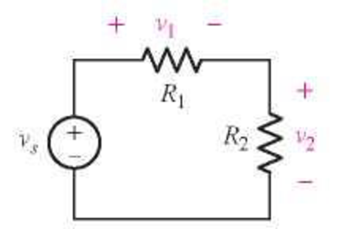
FIGURE 3.63
Want to see the full answer?
Check out a sample textbook solution
Chapter 3 Solutions
Loose Leaf for Engineering Circuit Analysis Format: Loose-leaf


- Determine the range of K for which a system with the following characteristics equation is stable. S³ + 5s² + 7s + K = 0arrow_forwardQ2/ Find the state-space representation of the electrical network shown in Figure 3.8. The output is vo(t). C₁ не vo (1)arrow_forwardGroup the terms in your KCL equations and rewrite your equations in terms of V₁, V2, V3 .. [example: (...)v₁ +(...)V₂ −(...)V3 =(...)] R3 R₁ i₁ v1 12 iA R2 ww V2 13 R5 i5 www RA is V3 івarrow_forward
- Refer to the circuit below. The value of the nodal voltage V1 is given by: R1 R 120 1 1A E 24 V #ov) O A. 6 V O B. 20 V O C. 24 V O D. None of the given answers O E. 30 V O F. 12 Varrow_forward3. For the circuit shown in the figure, find a) I in 20 N b) V at 20 2 c) I in 75 N d) V at 75 N e) I in 300 N f) V at 300 N 20 2 240 V 75Q 300 2arrow_forwardQ3. The switch in the circuit has been closed for a long time, and it is opened at t=0. Find i(t) a) i(t) = 4e-0.5t I ww b) i(t) = 4e-2t 12 V 403 2H c) i(t) = 8e-0.5t d) i(t) = 8e-2t 1 FL20, AY2020-2021 Page 2arrow_forward
- Electrical Engineering For the final problem, consider the following circuit diagram: 12 Q 30 V Vx 60 Q 2"Vx B 6) For this circuit, please find and draw: a. The Thevenin equivalent circuit between A and B, using external excitation to find R. b. The Norton cquivalent circuit berween A and B. c. Review section 3-8 from the text. What value load resistor connected between A and B would yield maximum power transfer? How much power woukd this be?arrow_forwardFor numbers 3-5, check the given RLC circuit: A) B) A) B) d²1 dI +4 dt² dt d²1 1 dl + dt² 4 dt 3. The differential equation to solve for the subsequent current is given by d²1 dl +2 +81 10 dt² dt d²1 1 dl + +41 = 0 dt² 4 dt 4. Assuming that there is no current and charge when the voltage is first applied, what is L{1}? 8s +32 32 4s² + s + 16 8 4s² + s + 16 10s s² + 4s +8 s² + 4s +8 +81 = 0 +41 8 10 V 5. The subsequent current in the circuit is A) I(t) = 4e-8t cos √2 t B) I(t) = 4e-2t sin 2 t 50 m HH 10¹ C C) D) D) 1.25 H C) D) I(t) = 4e-8t sin √2t I(t) = 4e-2t cos 2 tarrow_forwardR4 1k0 R2 2kO R1 R6 V1 1kQ -12V 2kQ R3 4kQ R5 R7 >1kQ Show your work, formula and notation: Solve for: RT Notation: RT: IT:arrow_forward
- USE NODAL ANALYSIS Given a = 3000, b = 3, c = 7, d = 1, e = 0.001, f = 6, g = 4, h = 3 and j = 7, in the circuit below, select the bottom node as the reference node and obtain . . fkn V₂ Io (in mA) Note: Enter values with at least 3 decimal digits. V₁ V₂ al, gkf www V₂ hkf www bkn www din v jmA V₂ ckfarrow_forwardQ3: In the circuit shown below, By using Nodal Analysis, find R, (where I=2.359A) 36V RI 10 Q 12 N 12 V 24 Varrow_forward3.37 Apply loop analysis to the circuit of Figure P3.37. Check your results. ΙΩΣ 6V ΣΩ 2 A 3 Ω ΣΩ Figure P3.37 ΤΩ 192 4 Ω 3 Α 12 Varrow_forward
 Introductory Circuit Analysis (13th Edition)Electrical EngineeringISBN:9780133923605Author:Robert L. BoylestadPublisher:PEARSON
 Delmar's Standard Textbook Of ElectricityElectrical EngineeringISBN:9781337900348Author:Stephen L. HermanPublisher:Cengage Learning
 Programmable Logic ControllersElectrical EngineeringISBN:9780073373843Author:Frank D. PetruzellaPublisher:McGraw-Hill Education
 Fundamentals of Electric CircuitsElectrical EngineeringISBN:9780078028229Author:Charles K Alexander, Matthew SadikuPublisher:McGraw-Hill Education
 Electric Circuits. (11th Edition)Electrical EngineeringISBN:9780134746968Author:James W. Nilsson, Susan RiedelPublisher:PEARSON
 Engineering ElectromagneticsElectrical EngineeringISBN:9780078028151Author:Hayt, William H. (william Hart), Jr, BUCK, John A.Publisher:Mcgraw-hill Education,