
Physics for Scientists and Engineers with Modern Physics
10th Edition
ISBN: 9781337553292
Author: Raymond A. Serway, John W. Jewett
Publisher: Cengage Learning
expand_more
expand_more
format_list_bulleted
Videos
Textbook Question
Chapter 27, Problem 25P
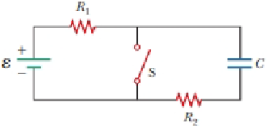
In the circuit of Figure P27.25, the switch S has been open for a long time. It is then suddenly closed. Take ε = 10.0 V, R1 = 50.0 kΩ, R2 = 100 kΩ, and C = 10.0 μF. Determine the time constant (a) before the switch is closed and (b) after the switch is closed. (c) Let the switch be closed at t = 0. Determine the current in the switch as a function of time.
Figure P27.25 Problems 25 and 26.
Expert Solution & Answer
Want to see the full answer?
Check out a sample textbook solution
Students have asked these similar questions
Chapter 30, Problem 054
In the figure, ε = 118 V, R₁ = 14.9 №, R₂ = 21.3 N, R3 = 35.8 №, and L=
1.90 H. Immediately after switch S is closed, what are (a) i₁ and (b) i₂?
(Let currents in the indicated directions have positive values and currents
in the opposite directions have negative values.) A long time later, what
are (c) ₁ and (d) i2? The switch is then reopened. Just then, what are
(e) ₁ and (f) i₂? A long time later, what are (g) ₁ and (h) i₂?
www
R₁
R$
R₂
L
You connect a battery, resistor, and capacitor as in (Figure 1), where R = 14.0 Ω and C = 3.00 ×10^-6 F. The switch S is closed at t = 0. When the current in the circuit has magnitude 3.00 A, the charge on the capacitor is 40.0 × 10^−6 C.
At what time t after the switch is closed is the charge on the capacitor equal to 40.0 x 10^-6 C?
When the current has magnitude 3.00 A, at what rate is energy being stored in the capacitor?
In the circuit of the figure below, the switch S has been open for a long time. It is then suddenly closed. Take = 10.0 V, R₁ = 41.0 km2,
R₂ = 170 kn, and C = 12.0 μF.
E
R₁
www
i
(a) Determine the time constant before the switch is closed.
2.532
S
I = &
(b) Determine the time constant after the switch is closed.
2.04
S
1
R₁
(c) Let the switch be closed at t = 0. Determine the current in the switch as a function of time. (Assume I is in A and t is in s. Do not
enter units in your expression. Use the following as necessary: t.)
+
www
R₂
C
R2
X
Chapter 27 Solutions
Physics for Scientists and Engineers with Modern Physics
Ch. 27.1 - To maximize the percentage of the power from the...Ch. 27.2 - With the switch in the circuit of Figure 27.4a...Ch. 27.2 - With the switch in the circuit of Figure 27.6a...Ch. 27.2 - Prob. 27.4QQCh. 27.4 - Consider the circuit in Figure 27.17 and assume...Ch. 27 - Two 1.50-V batterieswith their positive terminals...Ch. 27 - As in Example 27.2, consider a power supply with...Ch. 27 - Figure P27.3 shows the interior of a three-way...Ch. 27 - Prob. 4PCh. 27 - Consider the two circuits shown in Figure P27.5 in...
Ch. 27 - Consider strings of incandescent lights that are...Ch. 27 - You are working at an electronics fabrication...Ch. 27 - In your new job at an engineering company, your...Ch. 27 - A battery with = 6.00 V and no internal...Ch. 27 - A battery with emf and no internal resistance...Ch. 27 - Todays class on current and resistance is about to...Ch. 27 - Why is the following situation impossible? A...Ch. 27 - Calculate the power delivered to each resistor in...Ch. 27 - For the purpose of measuring the electric...Ch. 27 - Four resistors are connected to a battery as shown...Ch. 27 - You have a faculty position at a community college...Ch. 27 - The circuit shown in Figure P27.17 is connected...Ch. 27 - The following equations describe an electric...Ch. 27 - Taking R = 1.00 k and = 250 V in Figure P27.19,...Ch. 27 - In the circuit of Figure P27.20, the current I1 =...Ch. 27 - (a) Can the circuit shown in Figure P27.21 be...Ch. 27 - For the circuit shown in Figure P27.22, we wish to...Ch. 27 - An uncharged capacitor and a resistor are...Ch. 27 - Prob. 24PCh. 27 - In the circuit of Figure P27.25, the switch S has...Ch. 27 - In the circuit of Figure P27.25, the switch S has...Ch. 27 - A 10.0-F capacitor is charged by a 10.0-V battery...Ch. 27 - Prob. 28PCh. 27 - Prob. 29PCh. 27 - Prob. 30PCh. 27 - Prob. 31PCh. 27 - Prob. 32APCh. 27 - Find the equivalent resistance between points a...Ch. 27 - The circuit in Figure P27.34a consists of three...Ch. 27 - The circuit in Figure P27.35 has been connected...Ch. 27 - The resistance between terminals a and b in Figure...Ch. 27 - (a) Calculate the potential difference between...Ch. 27 - Why is the following situation impossible? A...Ch. 27 - When two unknown resistors are connected in series...Ch. 27 - Prob. 40APCh. 27 - The circuit in Figure P27.41 contains two...Ch. 27 - Prob. 42APCh. 27 - A power supply has an open-circuit voltage of 40.0...Ch. 27 - A battery is used to charge a capacitor through a...Ch. 27 - Prob. 45APCh. 27 - (a) Determine the equilibrium charge on the...Ch. 27 - In Figure P27.47, suppose the switch has been...Ch. 27 - Figure P27.48 shows a circuit model for the...Ch. 27 - The student engineer of a campus radio station...Ch. 27 - Prob. 50APCh. 27 - The switch in Figure P27.51a closes when Vc23Vand...
Additional Science Textbook Solutions
Find more solutions based on key concepts
What discovery in the 15th century greatly advanced progress in science?
Conceptual Physical Science Explorations
The validity of a scientific law.
Physical Universe
Is Earths inner core solid and the outer core liquid because the inner core is cooler than the outer core? Expl...
Conceptual Integrated Science
Whether two metal foil leaves an electroscope get opposite charge when the electroscope is charged.
The Physics of Everyday Phenomena
The formula for the sum Sn of the geometric series Sn=a+ar+.....arn−1 .
Mathematical Methods in the Physical Sciences
7. (II) (a) What is the current in the element of an electric clothes dryer with a resistance of 8.6 ?when it i...
Physics: Principles with Applications
Knowledge Booster


Learn more about
Need a deep-dive on the concept behind this application? Look no further. Learn more about this topic, physics and related others by exploring similar questions and additional content below.Similar questions
- In the circuit of Figure P21.57, the switch S has been open for a long time. It is then suddenly closed. Take = 10.0 V, R1 = 50.0 k, R2 = 100 k, and C = 10.0 F. Determine the time constant (a) before the switch is closed and (b) after the switch is closed. (c) Let the switch be closed at t = 0. Determine the current in the switch as a function of time.arrow_forwardIn the circuit of Figure P27.25, the switch S has been open for a long time. It is then suddenly closed. Determine the time constant (a) before the switch is closed and (b) after the switch is closed. (c) Let the switch be closed at t = 0. Determine the current in the switch as a function of time. Figure P27.25 Problems 25 and 26.arrow_forwardConsider a series RC circuit as in Figure P28.38 for which R = 1.00 M, C = 5.00 F, and = 30.0 V. Find (a) the time constant of the circuit and (b) the maximum charge on the capacitor after the switch is thrown closed. (c) Find the current in the resistor 10.0 s after the switch is closed.arrow_forward
- For the circuit shown in the figure, C = 12 µF and R = 8.5 MΩ. Initially the switch S is open with the capacitor charged to a voltage of 80 V. The switch is then closed at time t = 0.00 s. What is the charge on the capacitor, when the current in the circuit is 3.3 µA?arrow_forwardFor a long period of time the switch S in position "b". At t = 0 s, the switch Si moved from position "b" to position "a". 1 ΜΩ www 3 ΜΩ www 11 V 4 μF Sb Find the voltage across the 1 MN center-left resistor at time t₁ = 3 s. Answer in units of V. Much later, at some time to = 0s, the switch is moved from position "a" to position "b". Find the voltage across the 1 MS center-left resistor at time t' = 1.3 s. Answer in units of V.arrow_forwardChapter 27, Problem 063 In the circuit of the figure 8 = 4.20 kV, C = 7.90 µF, R₁ = R₂ = R3 = 1.01 MS. With C completely uncharged, switch S is suddenly closed (at t = 0). At t = 0, what are (a) current ₁ in resistor 1, (b) current 12 in resistor 2, and (c) current i3 in resistor 3? At t = ∞ (that is, after many time constants), what are (d)i₁, (e)i2, and (f)i3? What is the potential difference V₂ across resistor 2 at (g)t = 0 and (h)t = ∞? ww R₁ E R₂ Chapter 27, Problem 065 GO In the figure R₁ = 10.9 kN, R₂ = 15.0 kN, C = 0.430 µF, and the ideal battery has emf ε = 23.0 V. First, the switch is closed a long time so that the steady state is reached. Then the switch is opened at time t = 0. What is the current in resistor 2 at t = 4.00 ms? R₁ Rg Für R₂ Carrow_forward
- In the figure, & = 134 V, R₁ = 8.500, R₂ = 17.602, R3 = 26.4 02, and L = 2.14 H. Immediately after switch S is closed, what are (a) i₁ and (b) i2? (Let currents in the indicated directions have positive values and currents in the opposite directions have negative values.) A long time later, what are (c) i₁ and (d) i₂? The switch is then reopened. Just then, what are (e) i and (f) i2? A long time later, what are (g) i₁ and (h) i₂? (a) Number (b) Number i (c) Number (d) Number i (e) Number i =8 Units Units Units Units S Units R₁ i₂ {R₂ > > W R₁ > elearrow_forwardIn the figure R₁ = 9.42 kQ, R₂ = 15.7 kQ, C = 0.439 µF, and the ideal battery has emf & = 18.0 V. First, the switch is closed a long time so that the steady state is reached. Then the switch is opened at time t = 0. What is the current in resistor 2 at t = 4.10 ms? Number Units R₁ R₂ Carrow_forwardIn the figure, & = 111 V. R₁ = 9.83 0, R₂ = 27.80, R3 = 28.80, and L = 2.92 H. Immediately after switch 5 is closed, what are (a)i₁ and (b) i₂? (Let currents in the indicated directions have positive values and currents in the opposite directions have negative values.) A long time later, what are (c) i₁ and (d) i₂? The switch is then reopened. Just then, what are (e) i₁ and (f) i₂? A long time later, what are (g) 1₁ and (h) i₂? (a) Number i (b) Number i (c) Number (d) Number (e) Number i (f) Number i (g) Number i (h) Number i Units Units Units Units Units Units Units Units 8 ww www R₂ ele Larrow_forward
- In the figure R1 = 9.81 kΩ, R2 = 15.4 kΩ, C = 0.433 μF, and the ideal battery has emf ε = 18.0 V. First, the switch is closed a long time so that the steady state is reached. Then the switch is opened at time t = 0. What is the current in resistor 2 at t = 3.60 ms?arrow_forwardIn the circuit diagram R1 = 1760 Ω, R2 = 3130 Ω, C1 = 2.9 μF, C2 = 5.7 μF, and ℰ = 12 V. The switch is closed at t = 0. What is the current in A from the battery when t = 1.018 seconds?arrow_forwardIn the figure the ideal battery has emf 8 = 43 V, the resistances are R1 = 51 kN and R2 = 44 kN, and the capacitor is uncharged. When the switch is closed at time t = 0, what is the current in (a) resistance 1 and (b) resistance 2? (c) A long time later, what is the current in resistance 2? R2 R1 (a) Number Units (b) Number i Units (c) Number i Unitsarrow_forward
arrow_back_ios
SEE MORE QUESTIONS
arrow_forward_ios
Recommended textbooks for you
 Physics for Scientists and Engineers with Modern ...PhysicsISBN:9781337553292Author:Raymond A. Serway, John W. JewettPublisher:Cengage Learning
 Physics for Scientists and EngineersPhysicsISBN:9781337553278Author:Raymond A. Serway, John W. JewettPublisher:Cengage Learning
 Principles of Physics: A Calculus-Based TextPhysicsISBN:9781133104261Author:Raymond A. Serway, John W. JewettPublisher:Cengage Learning
 Physics for Scientists and Engineers: Foundations...PhysicsISBN:9781133939146Author:Katz, Debora M.Publisher:Cengage Learning
 Physics for Scientists and Engineers, Technology ...PhysicsISBN:9781305116399Author:Raymond A. Serway, John W. JewettPublisher:Cengage Learning
Physics for Scientists and Engineers with Modern ...
Physics
ISBN:9781337553292
Author:Raymond A. Serway, John W. Jewett
Publisher:Cengage Learning
Physics for Scientists and Engineers
Physics
ISBN:9781337553278
Author:Raymond A. Serway, John W. Jewett
Publisher:Cengage Learning
Principles of Physics: A Calculus-Based Text
Physics
ISBN:9781133104261
Author:Raymond A. Serway, John W. Jewett
Publisher:Cengage Learning
Physics for Scientists and Engineers: Foundations...
Physics
ISBN:9781133939146
Author:Katz, Debora M.
Publisher:Cengage Learning
Physics for Scientists and Engineers, Technology ...
Physics
ISBN:9781305116399
Author:Raymond A. Serway, John W. Jewett
Publisher:Cengage Learning
What is Electromagnetic Induction? | Faraday's Laws and Lenz Law | iKen | iKen Edu | iKen App; Author: Iken Edu;https://www.youtube.com/watch?v=3HyORmBip-w;License: Standard YouTube License, CC-BY