
Videos
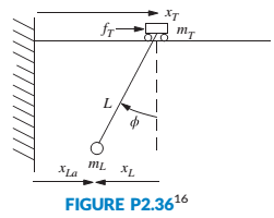
Figure P2.36 shows a crane hoisting a load. Although the actual system's model is highly nonlinear, if the rope is considered to be stiff with a fixed length L, the system can be modeled using the following equations:
where mLis the mass of the load, my is the mass of the cart, xT, and xLare displacements as defined in the figure,
- Obtain the transfer function from cart velocity to rope angle
Want to see the full answer?
Check out a sample textbook solution
Chapter 2 Solutions
Control Systems Engineering


- A velocity of a vehicle is required to be controlled and maintained constant even if there are disturbances because of wind, or road surface variations. The forces that are applied on the vehicle are the engine force (u), damping/resistive force (b*v) that opposing the motion, and inertial force (m*a). A simplified model is shown in the free body diagram below. From the free body diagram, the ordinary differential equation of the vehicle is: m * dv(t)/ dt + bv(t) = u (t) Where: v (m/s) is the velocity of the vehicle, b [Ns/m] is the damping coefficient, m [kg] is the vehicle mass, u [N] is the engine force. Question: Assume that the vehicle initially starts from zero velocity and zero acceleration. Then, (Note that the velocity (v) is the output and the force (w) is the input to the system): 1. What is the order of this system?arrow_forward3) For the mechanical system shown below find a state variable representation of the equations of motion →→→→ X(t) M K K Fmmmm ⇒ F(t)arrow_forwardUsing similarity transform we transform a system into a different system. Select one: True Falsearrow_forward
- 1 Overview In this project, you'll use several robot datasets for estimation and you will implement a Kalman Filter (KF) for state estimation. Consider the vehicle depicted in Fig. 1 with m = 0.5, k = 3.5, b = 2. The position s and velocity v represent the state x of the system and the input ƒ (t) is the force often denoted with u. F b m Figure 1: Robot cart 0 s(t) f(t) 1. Write the system in state space form and consider additive Gaussian white noise to the model n N (0, Q). Discretize the system state space form using Euler approach (30 points).arrow_forward1 An object of mass 125 kg is released from rest from a boat into the water and allowed to sink. While gravity is pulling the object down, a buoyancy force of times the weight of the object is pushing the object up (weight = mg). If we assume that water 40 resistance exerts a force on the object that is proportional to the velocity of the object, with proportionality constant 10 N-sec/m, find the equation of motion of the object. After how many seconds will the velocity of the object be 90 m/sec? Assume that the acceleration due to gravity is 9.81 m/ sec2. Find the equation of motion of the object. X(t) = %3Darrow_forwardHarmonic oscillators. One of the simplest yet most important second-order, linear, constant- coefficient differential equations is the equation for a harmonic oscilator. This equation models the motion of a mass attached to a spring. The spring is attached to a vertical wall and the mass is allowed to slide along a horizontal track. We let z denote the displacement of the mass from its natural resting place (with x > 0 if the spring is stretched and x 0 is the damping constant, and k> 0 is the spring constant. Newton's law states that the force acting on the oscillator is equal to mass times acceleration. Therefore the differential equation for the damped harmonic oscillator is mx" + bx' + kr = 0. (1) k Lui Assume the mass m = 1. (a) Transform Equation (1) into a system of first-order equations. (b) For which values of k, b does this system have complex eigenvalues? Repeated eigenvalues? Real and distinct eigenvalues? (c) Find the general solution of this system in each case. (d)…arrow_forward
- Consider a physical system with a three-dimensional state space. An orthonormal basis of the state space is chosen. In this basis the Hamiltonian is represented by the matrix H = [2 1 0 1 2 0 0 0 3] What are the possible results when the energy of the system is measured? A particle is in the state| psi > which is represented in this basis as, with i = Squareroot (-1), 1/Squareroot 3 [i -i i] Find , , and Delta H.arrow_forwardFor the simple mechanical system model shown in fig.2 with (M=2, B=0.7, k=1). Write the differential equation K f(t) M y(t) AB Fig.2 Simple mechanical systemarrow_forwardFind the differential equation of the mechanical system in Figure 1(a) To obtain the differential equation of motion of the mass and spring system given in Fig. 1. (a) one may utilize the Newton's law for mass and spring relations defined as shown in Fig. 1. (b) and (c) use f = cv for viscous friction, where v is the velocity of the motion and c is a constant. Z/////// k M F. F, F F F, F, k EF=ma F = k(x, - x,) = kx (b) (c) Figure 1: Mass-spring system (a), Force relations of mass (b) and spring (c)arrow_forward
- 01(1) 1 N-m-s/rad T(t) 02(1) 18 N-m-s/rad + 3 kg-m? 3 kg-m2 3 N-m/rad 9 N-m/rad (a) Figure P2.16a O John Wiley & Sons, Inc. All rights reserved. The matrix form of the system is 5s +9s +9 (s+9) а. (s+8) s? +s+1 5s2 +9s +9 b. -(s+9) -(s +9) 3s? + s+120,(s), 5s² +9s +9 (s+9) c. -(s+9) 3s? +s+12 5s +9s +9 d. -(s+9) F(s) -(s +9) 3s +s+120,(s), Select one: а. С O b. b O c. d d. aarrow_forward2) As shown in the figure, a uniform rod of length I and mass m is supported by a pin at one end and is suspended horizontally from a string of length h at a point s from the end. m 1/2 $ G: Ah h 真横からみた図 1) When the string rotates by 0, how much does the position of points on the rod move upward? (Just the answer is enough.) 2) When the string is displaced upward by Ah, how much does the bar's center of gravity displace? (Just write your answer). 3) Find the change in potential energy U at this time. Next, assuming that is small, express U as a power of 0. 4) Find the moment of inertia of mass m around the fulcrum. 5) Find the kinetic energy when the rod rotates by around the fulcrum. Using the relationship h0 = so, express the kinetic energy as the power of the derivative of 0. 6) Find the natural angular frequency of this system using the energy method.arrow_forwardYou are requested to design an automotive suspension or shock absorber system. In order to simplify the problem to one dimensional multiple mass-spring-damper system, a quarter vehicle model is used. The system parameters and free-body diagram of such system is shown below. M₁: Automobile body mass M₂: Wheel and suspension mass K₁: Spring constant of suspension system K2: Spring constant of wheel and tire B: Damping constant of shock absorber (a) Obtain the transfer function of X₁ (s) F(s) T₁(s) = = 2500 kg = 320 kg and T₂(s) = = 80,000 N/m = 500,000 N/m = 350 N-s/m Automobile- Suspension system Wheel- M₁ M₂ X₁ (s) - X₂ (S) F(s) in terms of the parameters of mass, damper and elastance (M, B and K). (b) Express the T₁ (s) and T₂ (s) with numerical values. c) Plot the x₁ (t) and x₁ (t) = x₂(t) outputs of this passive suspension system for the input torque f(t) = 2,000 N. fit) K₂ x₂(t) -Tirearrow_forward
 Elements Of ElectromagneticsMechanical EngineeringISBN:9780190698614Author:Sadiku, Matthew N. O.Publisher:Oxford University Press
 Mechanics of Materials (10th Edition)Mechanical EngineeringISBN:9780134319650Author:Russell C. HibbelerPublisher:PEARSON
 Thermodynamics: An Engineering ApproachMechanical EngineeringISBN:9781259822674Author:Yunus A. Cengel Dr., Michael A. BolesPublisher:McGraw-Hill Education
 Control Systems EngineeringMechanical EngineeringISBN:9781118170519Author:Norman S. NisePublisher:WILEY
 Mechanics of Materials (MindTap Course List)Mechanical EngineeringISBN:9781337093347Author:Barry J. Goodno, James M. GerePublisher:Cengage Learning
 Engineering Mechanics: StaticsMechanical EngineeringISBN:9781118807330Author:James L. Meriam, L. G. Kraige, J. N. BoltonPublisher:WILEY