
Control Systems Engineering
7th Edition
ISBN: 9781118170519
Author: Norman S. Nise
Publisher: WILEY
expand_more
expand_more
format_list_bulleted
Videos
Textbook Question
Chapter 2, Problem 46P
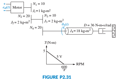
The motor whose torque-speed characteristics are shown in Figure P2.31 drives the load shown in the diagram. Some of the gears have inertia. Find the transfer function,
Expert Solution & Answer
Want to see the full answer?
Check out a sample textbook solution
Students have asked these similar questions
In the figure, a disk-shaped wheel of mass M and radius R rolls without slipping on a circular platform of radius 2L+R. The wheel is attached by a torsion spring to a pendulum of length 2L of mass m and moves with this pendulum.a) Derive the differential equation for the motion of the system given here.b) Find the natural frequency of the free motion of the system.
L=2 [m],
R= 0,5 [m],
m=5 [kg],
M= 65[kg],
kb= 165 [Nm/rad]
Note: There is no friction in this system
32. For the rotational mechanical system with gears
shown in Figure P2.18, find the transfer function,
G(s) = 03(s)/T(s). The gears have inertia and bear-
ing friction as shown. [Section: 2.7]
T(t)
to
|N1
小D
N2
N3
2, D2
Jz, D3 03(1)
N4
J4. D4
J5. D5
FIGURE P2.18
sair
Chapter 07, Problem 027
Z Your answer is partially correct. Try again.
A spring and block are in the arrangement of the figure. When the block is pulled out to x = +4.0 cm, we must apply a force of magnitude 370N to hold it there. We pull
the block to x = 11.0 cm and then release it. How much work does the spring do on the block when the block moves from x, = +5.0 cm to (a) x = +4.0 cm, (b) x = -4.0
cm, (c) x= -5.0 cm, and (d) x = -10.0 cm?
x=0
Block
F= 0
attached
elleeee
to spring
(a)
x positive
F, negative
(b)
ugen/shared/assignment/test/aglist.uni?id=..
x negative
9:34 PM
search
A ENG
4/4/2021
ASUS
13)
1ghome
f10 snd
17
4
7.
00
16
3.
Chapter 2 Solutions
Control Systems Engineering
Ch. 2 - Prob. 1RQCh. 2 - Prob. 2RQCh. 2 - Prob. 3RQCh. 2 - Define the transfer function.Ch. 2 - Prob. 5RQCh. 2 - What do we call the mechanical equations written...Ch. 2 - If we understand the form the mechanical equations...Ch. 2 - Why do transfer functions for mechanical networks...Ch. 2 - What function do gears perform?Ch. 2 - What are the component parts of the mechanical...
Ch. 2 - The motor’s transfer function relates armature...Ch. 2 - Summarize the steps taken to linearize a nonlinear...Ch. 2 - Prob. 1PCh. 2 - Prob. 2PCh. 2 - Prob. 3PCh. 2 - Prob. 4PCh. 2 - Prob. 5PCh. 2 - Prob. 6PCh. 2 - Prob. 7PCh. 2 - A system is described by the following...Ch. 2 - For each of the following transfer functions,...Ch. 2 - Write the differential equation for the system...Ch. 2 - Write the differential equation that is...Ch. 2 - Prob. 12PCh. 2 - Use MATLAB to generate the MATLAB ML transfer...Ch. 2 - Repeat Problem 13 for the MATLAB following...Ch. 2 - Use MATLAB to generate the partial fraction...Ch. 2 - Use MATLAB and the Symbolic Math Symbolic Math...Ch. 2 - Prob. 17PCh. 2 - Prob. 18PCh. 2 - Prob. 19PCh. 2 - Repeat Problem 19 using nodal equations. [Section:...Ch. 2 - Prob. 22PCh. 2 - Prob. 23PCh. 2 - Prob. 24PCh. 2 - Prob. 25PCh. 2 - Prob. 26PCh. 2 - Prob. 27PCh. 2 - Prob. 28PCh. 2 - Prob. 29PCh. 2 - Write, but do not solve, the equations of motion...Ch. 2 - For the unexcited (no external force applied)...Ch. 2 - For each of the rotational mechanical systems...Ch. 2 - For the rotational mechanical system shown in...Ch. 2 - Find the transfer function, 1sTs , for the system...Ch. 2 - For the rotational mechanical system with gears...Ch. 2 - For the rotational system shown in Figure P2.21,...Ch. 2 - Prob. 37PCh. 2 - Find the transfer function, Gs=4s/Ts , for the...Ch. 2 - For the rotational system shown in Figure P2.24,...Ch. 2 - Prob. 40PCh. 2 - Given the rotational system shown in Figure P226,...Ch. 2 - In the system shown in Figure P2.27, the inertia,...Ch. 2 - Prob. 43PCh. 2 - Given the combined translational and rotational...Ch. 2 - Prob. 45PCh. 2 - The motor whose torque-speed characteristics are...Ch. 2 - A dc motor develops 55 N-m of torque at a speed of...Ch. 2 - 48. In this chapter, we derived the transfer...Ch. 2 - Prob. 49PCh. 2 - Find the series and parallel analogs for the...Ch. 2 - Find the series and parallel analogs for the...Ch. 2 - A system’s output, c, is related to the system’s...Ch. 2 - Prob. 53PCh. 2 - Consider the differential equation...Ch. 2 - 55. Many systems are piecewise linear. That is,...Ch. 2 - For the translational mechanical system with a...Ch. 2 - 57. Enzymes are large proteins that biological...Ch. 2 - Prob. 58PCh. 2 - Figure P2.36 shows a crane hoisting a load....Ch. 2 - 60. In 1978, Malthus developed a model for human...Ch. 2 - 61. In order to design an underwater vehicle that...Ch. 2 - 62. The Gompertz growth model is commonly used to...Ch. 2 - A muscle hanging from a beam is shown in Figure...Ch. 2 - A three-phase ac/dc converter supplies dc to a...Ch. 2 - Prob. 65P
Knowledge Booster


Learn more about
Need a deep-dive on the concept behind this application? Look no further. Learn more about this topic, mechanical-engineering and related others by exploring similar questions and additional content below.Similar questions
- Find the transfer function 8,(s) / T(s) of the given mechanical network below. Show your complete solution on a clean sheet of paper. I should see the following • List of torques exerted in tabular form ( • Clearly stated equations ( • Solution on how to find the transfer function from these equations IN-m/rad T) 02(1) for f I kg-m2 IN-m-s/rad I N-m-s/rad I N-m-s/radarrow_forward6. The electro-mechanical system shown below consists of an electric motor with input voltage V which drives inertia I in the mechanical system (see torque T). Find the governing differential equations of motion for this electro-mechanical system in terms of the input voltage to the motor and output displacement y. Electrical System puthiy C V V₁ R bac (0) T bac T Motor - Motor Input Voltage - Motor Back EMF = Kbac ( - Motor Angular Velocity - Motor Output Torque = K₂ i Kbacs K₁ - Motor Constants Mechanical System M T Frictionless Supportarrow_forwardJ 1. Using Lagrangian mechanics, derive the equations of motion of a cart with two tires under the cart shown in Figure P.4.1.arrow_forward
- Pleasearrow_forwardThree springs with different spring constants are connected as shown below. You are going to use spring elements to simulate this system. Suppose that the spring constants of the first, second and third elements are k1=3,410 N/m, k2=3,160 N/m and k3=3,380 N/m, respectively. Two horizontal forces are applied to the system (as shown) at nodes. 2 and 3. Find the displacement of node 3 and write your answer in mm (millimetre). Hint: Write your answer with 5 decimal places. For example if you calculated the value 1.2345678, then rounding off to 5 decimal places yields 1.23457 and that is the value you need to type in the answer box. U₁=0 (1) F₂ = 2N U₂ = ? F3 = -1N (2) M U3 = ? (3) U4 = 0arrow_forwardFind the differential equation of the mechanical system in Figure 1(a) To obtain the differential equation of motion of the mass and spring system given in Fig. 1. (a) one may utilize the Newton's law for mass and spring relations defined as shown in Fig. 1. (b) and (c) use f = cv for viscous friction, where v is the velocity of the motion and c is a constant. Z/////// k M F. F, F F F, F, k EF=ma F = k(x, - x,) = kx (b) (c) Figure 1: Mass-spring system (a), Force relations of mass (b) and spring (c)arrow_forward
- 1 An object of mass 125 kg is released from rest from a boat into the water and allowed to sink. While gravity is pulling the object down, a buoyancy force of times the weight of the object is pushing the object up (weight = mg). If we assume that water 40 resistance exerts a force on the object that is proportional to the velocity of the object, with proportionality constant 10 N-sec/m, find the equation of motion of the object. After how many seconds will the velocity of the object be 90 m/sec? Assume that the acceleration due to gravity is 9.81 m/ sec2. Find the equation of motion of the object. X(t) = %3Darrow_forwardll b) Obtain the mathematical model of the system shown in Figure Q2b using Newton's second law of motion, F=ma. k₁ w 3- 777777 C1 7771 k₂ D 7777 Figure: Q2b Page 2 of 7 A C2 1112arrow_forwardX2(s) 8 Find the Transfer Function G(s) = for the trans- lational mechanical system shown in the Figure. (Hint: place a zero mass at r2(t)). ell 10 kg 2 N/m 5 N-s/m 2 N-s/m 9 For the system in the Figure below, find the Transfer Function G(s) = X1(s) F(s) K= 4 N/m K2= 5 N/m 3 N-s/m M =I kg rz=3 N-s/m M2 = 2 kg fr 2 N-s/marrow_forward
- 1. Write the mathematical equations for the mechanical rotational system given. Also find the transfer function (s)/T(s) of the given system. # (Torque applied) J₂ voooooo J₂arrow_forwardConsider the following spring system. m, C3 Cy m₂ C₂ Write the stiffness matrix K Write the matrix M ¹K C₁ = 6, m₁ = 6, C₂ = 12, m₂ = 3 Find the eigenvalues and eigenvectors of M ¹K: Smaller eigenvalue = with eigenvector • Larger eigenvalue = with eigenvector C3 = 18, C₁=6 If this spring system oscillates without any external forces present, then the position of each mass satisfies the following general formula: X 8 u(t) = (a₁ cos( t) + b₁ sin(t)) + (a2 cos (t) + b2 sin(t)) If the system begins oscillation with initial position u(0) = [] | and initial velocity (0) = [] then the position of the masses at time t is given by u₁(t): u₂(t):arrow_forward3:17 AM ← Jonathan Wickert, Kemper Lewis - An Introduction to Mechanical Engineering-Cengage L... Figure P8.3 Problem P8.3 The disk in a computer hard drive spins at 7200 rpm (Figure P8.3). At the radius of 30 mm, a stream of data is magnetically written on the disk, and the spacing between data bits is 25 µm. Determine the number of bits per second that pass by the read/write head. 30 mm 7200 rpm BA um 4G+ 49%arrow_forward
arrow_back_ios
SEE MORE QUESTIONS
arrow_forward_ios
Recommended textbooks for you
 Elements Of ElectromagneticsMechanical EngineeringISBN:9780190698614Author:Sadiku, Matthew N. O.Publisher:Oxford University Press
 Mechanics of Materials (10th Edition)Mechanical EngineeringISBN:9780134319650Author:Russell C. HibbelerPublisher:PEARSON
 Thermodynamics: An Engineering ApproachMechanical EngineeringISBN:9781259822674Author:Yunus A. Cengel Dr., Michael A. BolesPublisher:McGraw-Hill Education
 Control Systems EngineeringMechanical EngineeringISBN:9781118170519Author:Norman S. NisePublisher:WILEY
 Mechanics of Materials (MindTap Course List)Mechanical EngineeringISBN:9781337093347Author:Barry J. Goodno, James M. GerePublisher:Cengage Learning
 Engineering Mechanics: StaticsMechanical EngineeringISBN:9781118807330Author:James L. Meriam, L. G. Kraige, J. N. BoltonPublisher:WILEY
Elements Of Electromagnetics
Mechanical Engineering
ISBN:9780190698614
Author:Sadiku, Matthew N. O.
Publisher:Oxford University Press
Mechanics of Materials (10th Edition)
Mechanical Engineering
ISBN:9780134319650
Author:Russell C. Hibbeler
Publisher:PEARSON
Thermodynamics: An Engineering Approach
Mechanical Engineering
ISBN:9781259822674
Author:Yunus A. Cengel Dr., Michael A. Boles
Publisher:McGraw-Hill Education
Control Systems Engineering
Mechanical Engineering
ISBN:9781118170519
Author:Norman S. Nise
Publisher:WILEY
Mechanics of Materials (MindTap Course List)
Mechanical Engineering
ISBN:9781337093347
Author:Barry J. Goodno, James M. Gere
Publisher:Cengage Learning
Engineering Mechanics: Statics
Mechanical Engineering
ISBN:9781118807330
Author:James L. Meriam, L. G. Kraige, J. N. Bolton
Publisher:WILEY
Ficks First and Second Law for diffusion (mass transport); Author: Taylor Sparks;https://www.youtube.com/watch?v=c3KMpkmZWyo;License: Standard Youtube License