
Concept explainers
Videos
You have been hired to design a baseball “catcher” that consists of a 5-kg slender rod of length L = 1.2 m and a small net of negligible mass at point B to catch the ball. A spring of unstretched length 0.3 m is attached to the midpoint of bar AB at one end and to stationary point D at the other. A stopper at point E keeps the catcher in the vertical position before the pitch. Knowing the catcher just barely rotates through 90° when it catches a 40 m/s fastball of mass 0.145 kg, determine the required spring constant of the spring.
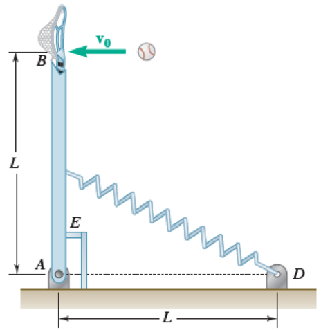
Fig. P17.113
Want to see the full answer?
Check out a sample textbook solution
Chapter 17 Solutions
Vector Mechanics for Engineers: Statics and Dynamics
Additional Engineering Textbook Solutions
Introduction to Heat Transfer
Applied Statics and Strength of Materials (6th Edition)
Vector Mechanics For Engineers
Vector Mechanics for Engineers: Statics, 11th Edition
Introduction To Finite Element Analysis And Design
Manufacturing Engineering & Technology


- A string is wrapped around a uniform disk of mass M = 2.1 kg and radius R = 0.12 m. (Recall that the moment of inertia of a uniform disk is (1/2) MR².) Attached to the disk are four low-mass rods of radius b = 0.16 m, each with a small mass m = 0.7 kg at the end. The device is initially at rest on a nearly frictionless surface. Then you pull the string with a constant force F = 30 N. At the instant when the center of the disk has moved a distance d = 0.041 m, a length w = 0.033 m of string has unwound off the disk. •m bi m m Part 1 M, R Part 2 d V= 0.708548386 Your answer is correct. Part 3 m (a) At this instant, what is the speed of the center of the apparatus? @01 = i 5.08017 Save for Later F Your answer is incorrect. (b) At this instant, what is the angular speed of the apparatus? 002 = i w+d Save for Later m/s eTextbook and Media F radians/s (c) You keep pulling with constant force 30 N for an additional 0.042 s. Now what is the angular speed of the apparatus? radians/s Attempts: 1…arrow_forwardA uniform disk of mass m = 4 kg and radius r = 150 mm is supported by a belt ABCD that is bolted to the disk at B and C. If the belt suddenly breaks at a point located between A and B, draw the FBD and KD for the disk immediately after the break.arrow_forwardA Hartnell type spring loaded governor rotates about a vertical axis. The two rotating masses weigh 10 N each rotate at a radius of 130 mm when the speed is 600 r.p.m. At this speed the arms, which are vertical and horizontal, have effective lengths of 110 mm and 80 mm respectively. The equilibrium sped is 630 r.p.m when the rotating masses are at their maximum radius of 160 mm. Determine the stiffness rate of spring, the compression of spring at 600 r.p.m.arrow_forward
- The illustrated system shows a pulley A that rotates under the effect of an external torque M. The belt that surrounds pulley A tries to stop it unsuccessfully, resulting in pulley A rotating at a constant speed while the belt is fixed. The belt in turn passes through an idle pulley B (frictionless pulley) and pulls a block of mass m2 that is attached to the wall by a spring. If it is considered that the spring has already been stretched by the effect of the tension of the band and that said block is in a condition of imminent movement in the direction to the left, determine: a) The magnitude of the torque M applied to pulley A in the counterclockwise direction. b) The elongation of the spring for the exposed condition. The values of R₂=400mm, R=300mm, μ-0,35, -0,20, k=1000N/m, m₁=17kg, m₂=12kg Pulley A Idle pulley D Resort m1 M a=60° m₂ 3arrow_forwardA thin circular disk of radius R and mass M has an axle through it close to its outer edge. The disk is rotated through 90 deg and then allowed to drop. (The figure shows the disk in its initial position before it is released, and its final position when point P passes through the lowest point). a) If the zero of height is taken to be the location of the COM when the disk is in its final position, what is the energy of the disk before it is release? b) What is the moment of inertia of the disk about the axle? c) What is the angular speed of the disk when it is in the final position? d) What is the speed of point P, on the outer edge of the disk, as it passes through the lowest point in its swing?arrow_forwardEach arm of a Proell governor is 240 mm long and each 240 h = 190 rotating ball has a mass of 3 kg. The central load acting on the sleeve is 30 kg. The pivots of all the arms are 30 mm from the axis of rotation. The vertical height of the T. Tcos e governor is 190 mm. The extension links of the lower arms are vertical and the governor speed is 180 rpm when the sleeve is in the mid-position. Determine the lengths of the extension links (e) and tension in the upper 3 kg 240 B arms (T). 30 30 kgarrow_forward
- Q4. A particle, of mass 2 kg, is attached to one end of a light inextensible string. The other end is fixed to the point O. The particle is set into motion, so that it describes a horizontal circle of radius 0.6 metres, with the string at an angle of 30° to the vertical. The centre of the circle is vertically below O. (a) Show that the tension in the string is 22.6 N, correct to three significant figures. (b) Find the speed of the particle. 30° 0.6m Iarrow_forwardP.5) A system consisting of two elastically constrained masses m₁ and m₂ is free to slide on a friction- less rod that rotates about the pivot point O. Mass m₁ is attached to O along the rod by a spring of stiffness k₁ with a free length of 1₁, and m₁ and m₂ are connected by a spring who sestiffness and free length are k₂ and 12, respectively. The angle describes the rod's orientation relative to the horizontal, and the positions of m₁ and m₂ along the rod are given by L₁ and L2, respectively. Find expressions for the system's total kinetic and potential energies. K y 5. 4₂ MM m₁ ←₂ MM 1112 j L SO Xarrow_forwardTwo uniform, solid cylinders of radius R and total mass M are connectedalong their common axis by a short, light rod and rest on a horizontaltabletop. A frictionless ring at the rod’s center is attached toa spring of force constant k; the spring’s other end is fixed. The cylindersare pulled to the left a distance x, stretching the spring, then releasedfrom rest. Due to friction between the tabletop and the cylinders, the cylindersroll without slipping as they oscillate. Show that the motion of thecenter of mass of the cylinders is simple harmonic, and find its period.arrow_forward
- In the figure below,the point mass m₂ glides without friction on horizontal plane, it is connected to a mass m₁, which hangs vertically by inextensible wire of length L, passing through the groove of pulley with radius a. The mass of the pulley and the mass of the wire are assumed to be negligible. To the mass m₂, it is attached a simple pendulum with a point mass m3 and an inextensible thread of length and negligible mass. The pendulum swings freely in the vertical plane and the system is subject to the earth's attraction. We study the motion of the system in the inertial reference frame R(O, x, y, z). We note (X₁, Y₁, Z;); i = 1,2,3 as a system coordinates of masses m. We put: m₁ = m₂ = .m; m3 = m. ym = a.m m₁ = Questions: 1. Write the constraints equations of the motion. m₁{ ; m₂{ 2. Calculate the degree of freedom for the system. m₂ = a.m в LL.cos 8 : 1. sin 8 ¡m3 { marrow_forward1. An excavator encounters a reaction force of 7600 lb from the ground, normal to line AC, as shown. The shaded structural members (Dipperstick (FH), Mainboom (ADK), bucket, and hydraulic cylinders) have a combined weight of 15000 lb and a horizontal mass center located midway between points C and G. A OLUNU G 3 ft 6 in. 40° E Mainboom 3 ft 4 in. 39 ft F O K Dipperstick H Bucket 7600 lb C Questions: (a) Dismember the shaded structural members (with labeled points A-H) from the tractor and sketch a free-body diagram showing external and exposed internal forces. (b) Compute the force in the hydraulic cylinder strut BD and the pin reactions at A in the given position.arrow_forwardProblem #1 A uniform hemisphere of mass M and radius R rests on a horizontal plane. A particle of mass m is attached to the rim as shown in the figure below. The angles 0 is indicated Use the principle of virtual work to determine the angle e (in terms of the mass ratio p = m/M) when the system is in static equilibrium. Hint: First determine the position of the hemisphere's center of mass as measured from the flat part of the hemisphere.arrow_forward
 Elements Of ElectromagneticsMechanical EngineeringISBN:9780190698614Author:Sadiku, Matthew N. O.Publisher:Oxford University Press
 Mechanics of Materials (10th Edition)Mechanical EngineeringISBN:9780134319650Author:Russell C. HibbelerPublisher:PEARSON
 Thermodynamics: An Engineering ApproachMechanical EngineeringISBN:9781259822674Author:Yunus A. Cengel Dr., Michael A. BolesPublisher:McGraw-Hill Education
 Control Systems EngineeringMechanical EngineeringISBN:9781118170519Author:Norman S. NisePublisher:WILEY
 Mechanics of Materials (MindTap Course List)Mechanical EngineeringISBN:9781337093347Author:Barry J. Goodno, James M. GerePublisher:Cengage Learning
 Engineering Mechanics: StaticsMechanical EngineeringISBN:9781118807330Author:James L. Meriam, L. G. Kraige, J. N. BoltonPublisher:WILEY