
Loose Leaf for Engineering Circuit Analysis Format: Loose-leaf
9th Edition
ISBN: 9781259989452
Author: Hayt
Publisher: Mcgraw Hill Publishers
expand_more
expand_more
format_list_bulleted
Videos
Textbook Question
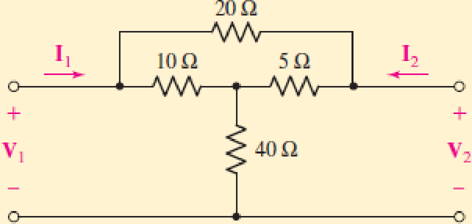
Chapter 16.2, Problem 3P
By applying the appropriate 1 V sources and short circuits to the circuit shown in Fig. 16.10, find (a) y11; (b) y21; (c) y22; (d) y12.
Expert Solution & Answer
Want to see the full answer?
Check out a sample textbook solution
Students have asked these similar questions
DESIGN A 16X1 MUX USING
ONLY ONE 8X1 MUX SO AS TO
SATISFY THE FUNCTION
F(A,B,C,D)= SUM(
1,3,4,6,8,10,12,14 ), D IS THE
MSB AND CONTROLLING
FACTOR( DESIGN W.R.T. D)
IMPLIMENT THE CIRCUIT
USING CIRCUIT MAKER AND
UPLOAD TO ELEARNING.
0785363649
Yl dWl fatoom_basemsh
Digital Circuits Lec 6
The institute of Samawa Technical
First Year
Department
Information and
Eng. Murtadha kamil Ali
Communications Technology
Homework:
1) Apply DeMorgan's theorems to each of the following
expression
A) (A+B+C)D
B) ABC+DEF
C) AB+CD+EF
D) (A+B) +C
E) (A+B) +CD
F) (A+B)CD+E+F
2) Draw the logic circuit
A) Y=(A+B+C)DE Y =ABCDE
B) X= ACD+BC
3) The following figure gives the function
A)
B)
LDS
59
...luln
D
i)
1. For the Boolean function, Z = A + B +H(C+DF) + EG
Draw the schematic of the pull-up and pull-down networks,
Determine the equivalent width of the pull-down network if the width of each transistor at
the network is W₁ = 2μm.
ii)
Chapter 16 Solutions
Loose Leaf for Engineering Circuit Analysis Format: Loose-leaf
Ch. 16.1 - Find the input impedance of the network shown in...Ch. 16.1 - Write a set of nodal equations for the circuit of...Ch. 16.2 - By applying the appropriate 1 V sources and short...Ch. 16.2 - Prob. 4PCh. 16.2 - Prob. 5PCh. 16.3 - Prob. 6PCh. 16.3 - Use Y and Y transformations to determine Rin for...Ch. 16.4 - Find z for the two-port shown in (a) Fig. 16.23a;...Ch. 16.4 - Prob. 9PCh. 16.5 - Prob. 10P
Ch. 16.5 - Prob. 11PCh. 16.6 - Prob. 12PCh. 16 - For the following system of equations, (a) write...Ch. 16 - With regard to the passive network depicted in...Ch. 16 - Determine the input impedance of the network shown...Ch. 16 - For the one-port network represented schematically...Ch. 16 - Prob. 6ECh. 16 - Prob. 7ECh. 16 - Prob. 8ECh. 16 - Prob. 9ECh. 16 - (a) If both the op amps shown in the circuit of...Ch. 16 - Prob. 11ECh. 16 - Prob. 12ECh. 16 - Prob. 13ECh. 16 - Prob. 14ECh. 16 - Prob. 15ECh. 16 - Prob. 16ECh. 16 - Prob. 17ECh. 16 - Prob. 18ECh. 16 - Prob. 19ECh. 16 - Prob. 20ECh. 16 - For the two-port displayed in Fig. 16.49, (a)...Ch. 16 - Prob. 22ECh. 16 - Determine the input impedance Zin of the one-port...Ch. 16 - Determine the input impedance Zin of the one-port...Ch. 16 - Employ Y conversion techniques as appropriate to...Ch. 16 - Prob. 26ECh. 16 - Prob. 27ECh. 16 - Prob. 28ECh. 16 - Compute the three parameter values necessary to...Ch. 16 - It is possible to construct an alternative...Ch. 16 - Prob. 31ECh. 16 - Prob. 32ECh. 16 - Prob. 33ECh. 16 - Prob. 34ECh. 16 - The two-port networks of Fig. 16.50 are connected...Ch. 16 - Prob. 36ECh. 16 - Prob. 37ECh. 16 - Obtain both the impedance and admittance...Ch. 16 - Prob. 39ECh. 16 - Determine the h parameters which describe the...Ch. 16 - Prob. 41ECh. 16 - Prob. 42ECh. 16 - Prob. 43ECh. 16 - Prob. 44ECh. 16 - Prob. 45ECh. 16 - Prob. 46ECh. 16 - Prob. 47ECh. 16 - Prob. 48ECh. 16 - Prob. 49ECh. 16 - Prob. 50ECh. 16 - (a) Employ suitably written mesh equations to...Ch. 16 - Prob. 52ECh. 16 - Prob. 53ECh. 16 - The two-port of Fig. 16.65 can be viewed as three...Ch. 16 - Consider the two separate two-ports of Fig. 16.61....Ch. 16 - Prob. 56ECh. 16 - Prob. 57ECh. 16 - Prob. 58ECh. 16 - (a) Obtain y, z, h, and t parameters for the...Ch. 16 - Four networks, each identical to the one depicted...Ch. 16 - A cascaded 12-element network is formed using four...Ch. 16 - Prob. 62ECh. 16 - Continuing from Exercise 62, the behavior of a ray...
Additional Engineering Textbook Solutions
Find more solutions based on key concepts
A constant voltage of 10V is applied to a 50H inductance, as shown in Figure P3.51 Figure P3 51 The current in ...
Electrical Engineering: Principles & Applications (7th Edition)
Design an ideal inverting op-amp circuit such that the voltage gain is Av=25 . The maximum current in any resis...
Microelectronics: Circuit Analysis and Design
Does the severity of an electric shock increase ordecrease with eh of the following changes? a. A decrease in t...
Electric Motors and Control Systems
When travelers from the USA and Canada visit Europe, they encounter a different power distribution system. Wall...
Electric machinery fundamentals
Electric power systems provide energy in a variety of commercial and industrial settings. Make a list of system...
Principles and Applications of Electrical Engineering
Assume a telephone signal travels through a cable at two-thirds the speed of light. How long does it take the s...
Electric Circuits (10th Edition)
Knowledge Booster


Learn more about
Need a deep-dive on the concept behind this application? Look no further. Learn more about this topic, electrical-engineering and related others by exploring similar questions and additional content below.Similar questions
- digital ckts. Q.2. Realize the following functions using minimum number of components to draw their digital circuits. 1. AB+ABAB 2 ABC + ABE + ABC 3. (A + B) (A + B) 4. (A+B+C). (A + 5 + c) (A + 3+C)arrow_forwardDESIGN A 16X1 MUX IN ORDER TO SATISFY THE FUNCTION F(A,B,C,D)=SUM(0,3,6,7,8,10,13,15) USING: A) 8X1 MULTIPLEXERSarrow_forward6) A combinational circuit has four inputs (A,B,C,D) and three outputs (X,Y,Z). XYZ represents a binary number whose value equals the number of 1's at the input. For example if ABCD = 1011 then xyz = 011. a. Find the minterm expansions for X,Y and Z. b. Find the maxterm expansions for X,Y and Z.arrow_forward
- 16 7 Vcc GND Strobe 4 DO 3 D1 5 D2 Output Y Data 1 D3 74151 Input 6 15 D4 14 D5 13 D6 12 D7 S2 S, So 9 10 11 Select Inputs Strobe Select Output Y S S2 S1 So 1 Do 1 D1 1 D2 1 D3 1 D4 1 1 D5 1 1 D6 1 1 1 D7 Fig.3 IC Type 74151 8-to-1 Multiplexer 7- Use the 8-to-1 MUX of Fig.3 to realized the following function: fA, B, C) Σ(0,1,3,6) .(2) 8- Use the 8-to-1 MUX of Fig.3 to realized the following function: f(A, B, C, D) = E(0,2,5,9,10,14) -(3)arrow_forwardA combinational circuit has four inputs (A,B,C,D) and three outputs (X.Y,Z). XYZ represents a binary number whose value equals the number of 1's at the input. For example if ABCD=1011, XYZ=011.(a) find the minterm expansions for X,Y, and Z.(b) find the maxterm expansions for Y and Z.arrow_forwardQ16/ a combinational circuit has four inputs (A, B, C, D), which represent a binary- coded- decimal digit. The circuit has two groups of four outputs S, T, U, V, and W, X, Y, Z each group represents a BCD digit. The output digits represent a decimal number which is five times the input number. For example if ABCD=D0111, the output are 0011 0101. ASsume that invalid BCD digits do not occur as inputs. a- Construct the truth table b- Write minterms and max terms for all output C- Find SOP and POS for all outputarrow_forward
- DESIGN A 16X1 MUX IN ORDER TO SATISFY THE FUNCTION F(A,B,C,D)=SUM(0,3,6,7,8,10,13,15) USING: B) 4X1 MULTIPLEXERSarrow_forwardvi(t) CCT1 Ri R₁ CCT2 Li 00000 wwwww L2 00000 R₂ R Rf OA1 OA2 ww R ip#, Vp# in#, Vn# Ra Rd CCT3 OA3 Ro OA# Ro m Vo# To vo(t) A. Redraw CCT2 in the s-domain labeling polarities, current directions, circuit variables and nodes (if node voltage analysis is used). B. Derive the transfer function T1(s) for CCT2. Simplify resulting expression by hand or with an external program.arrow_forward16 7 Vcc GND Strobe S 4 DO D1 5 D2 1 D3 Data Output Y 74151 Input 15 D4 14 D5 13 D6 12 D7 S2 S So 9 10 11 Select Inputs Strobe Select Output S2 S1 So Y 1 0. Do 1- D1 D2 1 1 D3 1 D4 1 1 D5 1 1 D6 1 1 1 D7 Fig.3 IC Type 74151 8-to-1 Multiplexer 8- Use the 8-to-1 MUX of Fig.3 to realized the following function: f(A, B, C, D) Σ(0,2,5,9,10,14) (3)arrow_forward
- For 32-points, how many times the FFT is faster than the direct evaluation using DFT if complex addition times are 0.1 sec and complex multiplication times are 1 * ?sec 1.123 80 160 11.7 () 96 How many complex additions are required to compute the best DIT-FFT * ?algorithm for for 32-points 96 O 160 1.123 80 11.7 Oarrow_forward1 Construct a table similar to Table 16.2 for a 4-bit A/D converter if Va = 5 V with a reference voltage of 16 V. Analog input VI Clock Vo Sample-and-hold + FUL Va Vb 4-bit SAR 4-bit DAC 4-bit register Logic control Ring counter (a) 4-bit A/D converter MSB B3 B₂ B₁ Bo LSB Outputarrow_forwardA) The probabilities for two events, C and D: P(C)=0.60, P(D)=0.40, P(CUD) =0.65 Are the events, C and D, independent in this situation? Prove it?arrow_forward
arrow_back_ios
SEE MORE QUESTIONS
arrow_forward_ios
Recommended textbooks for you
 Introductory Circuit Analysis (13th Edition)Electrical EngineeringISBN:9780133923605Author:Robert L. BoylestadPublisher:PEARSON
 Delmar's Standard Textbook Of ElectricityElectrical EngineeringISBN:9781337900348Author:Stephen L. HermanPublisher:Cengage Learning
 Programmable Logic ControllersElectrical EngineeringISBN:9780073373843Author:Frank D. PetruzellaPublisher:McGraw-Hill Education
 Fundamentals of Electric CircuitsElectrical EngineeringISBN:9780078028229Author:Charles K Alexander, Matthew SadikuPublisher:McGraw-Hill Education
 Electric Circuits. (11th Edition)Electrical EngineeringISBN:9780134746968Author:James W. Nilsson, Susan RiedelPublisher:PEARSON
 Engineering ElectromagneticsElectrical EngineeringISBN:9780078028151Author:Hayt, William H. (william Hart), Jr, BUCK, John A.Publisher:Mcgraw-hill Education,
Introductory Circuit Analysis (13th Edition)
Electrical Engineering
ISBN:9780133923605
Author:Robert L. Boylestad
Publisher:PEARSON
Delmar's Standard Textbook Of Electricity
Electrical Engineering
ISBN:9781337900348
Author:Stephen L. Herman
Publisher:Cengage Learning
Programmable Logic Controllers
Electrical Engineering
ISBN:9780073373843
Author:Frank D. Petruzella
Publisher:McGraw-Hill Education
Fundamentals of Electric Circuits
Electrical Engineering
ISBN:9780078028229
Author:Charles K Alexander, Matthew Sadiku
Publisher:McGraw-Hill Education
Electric Circuits. (11th Edition)
Electrical Engineering
ISBN:9780134746968
Author:James W. Nilsson, Susan Riedel
Publisher:PEARSON
Engineering Electromagnetics
Electrical Engineering
ISBN:9780078028151
Author:Hayt, William H. (william Hart), Jr, BUCK, John A.
Publisher:Mcgraw-hill Education,
L21E127 Control Systems Lecture 21 Exercise 127: State-space model of an electric circuit; Author: bioMechatronics Lab;https://www.youtube.com/watch?v=sL0LtyfNYkM;License: Standard Youtube License