
Loose Leaf for Engineering Circuit Analysis Format: Loose-leaf
9th Edition
ISBN: 9781259989452
Author: Hayt
Publisher: Mcgraw Hill Publishers
expand_more
expand_more
format_list_bulleted
Concept explainers
Videos
Textbook Question
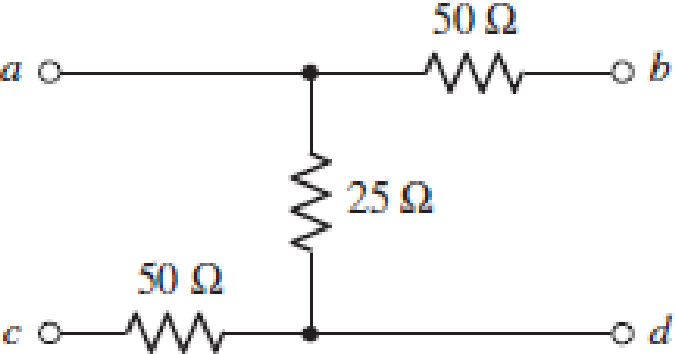
Chapter 16, Problem 40E
Determine the h parameters which describe the purely resistive network shown in Fig. 16.56 by connecting appropriate 1 V, 1 A, and short circuits to terminals as required.
Expert Solution & Answer
Want to see the full answer?
Check out a sample textbook solution
Students have asked these similar questions
Q4. Use a Karnaugh map to minimize the following standard SOP expression: (15 M)
ABC + ABC + ABC + ABC + ABC
Q5. Plot the corresponding SUM and CARRY outputs of half-adder circuit, for the given A and
B inputs. And give the logical expression for both. (15 M)
HA
A
B
3 Find the two-port (pic3) coefficients for A-form equation by voltages and current
at open circuit and short circuit regeemes. if øL¡=150 2, wL 2=50 Q, 1/mC =40 Q.
Check your answer by coefficients ratio.
Q4. Use a Karnaugh map to minimize the following standard SOP expression: (15 M)
ABC + ABC + ABC + ABC + ABC
Q5. Plot the corresponding SUM and CARRY outputs of half-adder circuit, for the given A and
B inputs. And give the logical expression for both.(15 M)
+H
B
Chapter 16 Solutions
Loose Leaf for Engineering Circuit Analysis Format: Loose-leaf
Ch. 16.1 - Find the input impedance of the network shown in...Ch. 16.1 - Write a set of nodal equations for the circuit of...Ch. 16.2 - By applying the appropriate 1 V sources and short...Ch. 16.2 - Prob. 4PCh. 16.2 - Prob. 5PCh. 16.3 - Prob. 6PCh. 16.3 - Use Y and Y transformations to determine Rin for...Ch. 16.4 - Find z for the two-port shown in (a) Fig. 16.23a;...Ch. 16.4 - Prob. 9PCh. 16.5 - Prob. 10P
Ch. 16.5 - Prob. 11PCh. 16.6 - Prob. 12PCh. 16 - For the following system of equations, (a) write...Ch. 16 - With regard to the passive network depicted in...Ch. 16 - Determine the input impedance of the network shown...Ch. 16 - For the one-port network represented schematically...Ch. 16 - Prob. 6ECh. 16 - Prob. 7ECh. 16 - Prob. 8ECh. 16 - Prob. 9ECh. 16 - (a) If both the op amps shown in the circuit of...Ch. 16 - Prob. 11ECh. 16 - Prob. 12ECh. 16 - Prob. 13ECh. 16 - Prob. 14ECh. 16 - Prob. 15ECh. 16 - Prob. 16ECh. 16 - Prob. 17ECh. 16 - Prob. 18ECh. 16 - Prob. 19ECh. 16 - Prob. 20ECh. 16 - For the two-port displayed in Fig. 16.49, (a)...Ch. 16 - Prob. 22ECh. 16 - Determine the input impedance Zin of the one-port...Ch. 16 - Determine the input impedance Zin of the one-port...Ch. 16 - Employ Y conversion techniques as appropriate to...Ch. 16 - Prob. 26ECh. 16 - Prob. 27ECh. 16 - Prob. 28ECh. 16 - Compute the three parameter values necessary to...Ch. 16 - It is possible to construct an alternative...Ch. 16 - Prob. 31ECh. 16 - Prob. 32ECh. 16 - Prob. 33ECh. 16 - Prob. 34ECh. 16 - The two-port networks of Fig. 16.50 are connected...Ch. 16 - Prob. 36ECh. 16 - Prob. 37ECh. 16 - Obtain both the impedance and admittance...Ch. 16 - Prob. 39ECh. 16 - Determine the h parameters which describe the...Ch. 16 - Prob. 41ECh. 16 - Prob. 42ECh. 16 - Prob. 43ECh. 16 - Prob. 44ECh. 16 - Prob. 45ECh. 16 - Prob. 46ECh. 16 - Prob. 47ECh. 16 - Prob. 48ECh. 16 - Prob. 49ECh. 16 - Prob. 50ECh. 16 - (a) Employ suitably written mesh equations to...Ch. 16 - Prob. 52ECh. 16 - Prob. 53ECh. 16 - The two-port of Fig. 16.65 can be viewed as three...Ch. 16 - Consider the two separate two-ports of Fig. 16.61....Ch. 16 - Prob. 56ECh. 16 - Prob. 57ECh. 16 - Prob. 58ECh. 16 - (a) Obtain y, z, h, and t parameters for the...Ch. 16 - Four networks, each identical to the one depicted...Ch. 16 - A cascaded 12-element network is formed using four...Ch. 16 - Prob. 62ECh. 16 - Continuing from Exercise 62, the behavior of a ray...
Additional Engineering Textbook Solutions
Find more solutions based on key concepts
When travelers from the USA and Canada visit Europe, they encounter a different power distribution system. Wall...
Electric machinery fundamentals
Electric power systems provide energy in a variety of commercial and industrial settings. Make a list of system...
Principles and Applications of Electrical Engineering
The voltage source of the circuit shown in Fig. P1.29 is given by s(t)=25cos(4104t45)(V). Obtain an expression ...
Fundamentals of Applied Electromagnetics (7th Edition)
Assume a telephone signal travels through a cable at two-thirds the speed of light. How long does it take the s...
Electric Circuits (10th Edition)
Write the nodal equations for the network of Fig. 8.137 using the general approach. Find the nodal voltages usi...
Introductory Circuit Analysis (13th Edition)
The current source in the circuit shown generates the current pulse
Find (a) v (0); (b) the instant of time gr...
Electric Circuits. (11th Edition)
Knowledge Booster


Learn more about
Need a deep-dive on the concept behind this application? Look no further. Learn more about this topic, electrical-engineering and related others by exploring similar questions and additional content below.Similar questions
- 2 port network T-Network attenuator has a R1=25.975ohms and R2=35.136ohms. Calculate the characteristic impedance and attenuation. Grateful help with this thanksarrow_forwardDetermine the Y-parameters at a frequency of 10 kHz for the two-port network shown in figure below. Present your answer in matrix form. R1 5 Ohm 1 Ohm 400 μF R3 4 Ohm R2 200 μF R5 L5 mom. 5 Ohm 796 µF 6.4 mHarrow_forwardDetermine the Y-parameters at a frequency of 10 kHz for the two-port network shown in figure below. Present your answer in matrix form. R1 5 Ohm 1 Ohm 400 μF 4 Ohm R2 R3 C2 HE 200 μF R5 L5 wome 5 Ohm C4 796 µF 6.4 mHarrow_forward
- Use Kirchoff’s rules to calculate I1, I2, and I3 using the above values for the emf and Rs. Remember, there is one more junction than is needed (the last would not be independent). Use the indicated current directions, which may or may not be correct.arrow_forwardUse Node-Voltage Method to find the voltage v_1. V, 20 40 V 202 800 24.75 V Select one: O a. 24.75 v O b. None of them O c. 28 v O d. 40 v O e. 30 varrow_forwardMESH ANALYSIS ( NEED NEAT HANDWRITTEN SOLUTION AND EXPLANATION OTHERWISE DOWNVOTE).arrow_forward
- Consider the following electrical system: By using controllability gramian, check if the system representation R(A, B, C ) is controllable.arrow_forwardASAParrow_forwardQ4. Determine the Y-parameters at a frequency of 10 kHz for the two-port network shown in figure 4 below. Present your answer in matrix form. R1 5 Ohm 1 Ohm 400 μF 4 Ohm R2 R3 C2 C3 HH 200 μF R5 L5 mam. 5 Ohm C4 796 µF 6.4 mHarrow_forward
- 18V Cad =2 pF Cas= 4 pF Cas = 0.5 pF Gui = 5 pF Gwo = 6 pF 1.8KA 0.47uF-POL loss = 12 mA V, = -6V 0.47UF-POL Yos = 40 uS 1.1MO 1.5 V For the network below, determine fip Show the details of your work. Write your solution on a white typewriting paper, scan it in JPEG format and upload it to the space provided below.arrow_forward(5) giscuss the gate for power mos FET• drine codarrow_forwardDetermine the Y-parameters at a frequency of 10 kHz for the two-port network shown in figure below. Present your answer in matrix form. R1 ww 5 Ohm 1 Ohm 400 µF 8 4 Ohm 200 µF & HE 5 Ohm 796 µF L5arrow_forward
arrow_back_ios
SEE MORE QUESTIONS
arrow_forward_ios
Recommended textbooks for you
 Introductory Circuit Analysis (13th Edition)Electrical EngineeringISBN:9780133923605Author:Robert L. BoylestadPublisher:PEARSON
 Delmar's Standard Textbook Of ElectricityElectrical EngineeringISBN:9781337900348Author:Stephen L. HermanPublisher:Cengage Learning
 Programmable Logic ControllersElectrical EngineeringISBN:9780073373843Author:Frank D. PetruzellaPublisher:McGraw-Hill Education
 Fundamentals of Electric CircuitsElectrical EngineeringISBN:9780078028229Author:Charles K Alexander, Matthew SadikuPublisher:McGraw-Hill Education
 Electric Circuits. (11th Edition)Electrical EngineeringISBN:9780134746968Author:James W. Nilsson, Susan RiedelPublisher:PEARSON
 Engineering ElectromagneticsElectrical EngineeringISBN:9780078028151Author:Hayt, William H. (william Hart), Jr, BUCK, John A.Publisher:Mcgraw-hill Education,
Introductory Circuit Analysis (13th Edition)
Electrical Engineering
ISBN:9780133923605
Author:Robert L. Boylestad
Publisher:PEARSON
Delmar's Standard Textbook Of Electricity
Electrical Engineering
ISBN:9781337900348
Author:Stephen L. Herman
Publisher:Cengage Learning
Programmable Logic Controllers
Electrical Engineering
ISBN:9780073373843
Author:Frank D. Petruzella
Publisher:McGraw-Hill Education
Fundamentals of Electric Circuits
Electrical Engineering
ISBN:9780078028229
Author:Charles K Alexander, Matthew Sadiku
Publisher:McGraw-Hill Education
Electric Circuits. (11th Edition)
Electrical Engineering
ISBN:9780134746968
Author:James W. Nilsson, Susan Riedel
Publisher:PEARSON
Engineering Electromagnetics
Electrical Engineering
ISBN:9780078028151
Author:Hayt, William H. (william Hart), Jr, BUCK, John A.
Publisher:Mcgraw-hill Education,
Lecture 4b -- Transmission Line Parameters; Author: EMPossible;https://www.youtube.com/watch?v=naG572ZnXqw;License: Standard Youtube License