
Concept explainers
Videos
A lens, a bulb, and a screen are arranged as shown below. A sharp, inverted image of the filament (not shown) appears on the screen when it at the location shown.
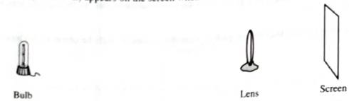
Predict how each of the following changes would affect what you see on the screen. Support tour predictions with one or more ray diagrams.
• The screen is moved closer to farther from the lens
• The top half on the lens is covered by a mask.
Does your answer depend on which side of the lens the mask is placed? If so, how? If not, why not?
Want to see the full answer?
Check out a sample textbook solution
Chapter 10 Solutions
Tutorials in Introductory Physics
Additional Science Textbook Solutions
The Cosmic Perspective
College Physics
Sears And Zemansky's University Physics With Modern Physics
University Physics with Modern Physics (14th Edition)
The Cosmic Perspective (8th Edition)
Essential University Physics (3rd Edition)


- construct ray diagrams for each marked dot to show the location and appearance of the image. That’s 4-5 ray diagrams per letter. Draw your rays lightly (but visibly) and mark your image points boldly.CONVERGING LENS 1.Where does the image of the letter “A” appear?2. Is the image of the letter A larger, smaller, or the same size as the object?3.Is the image of the letter A upright or inverted?4. In what way is the image of the letter A distorted?arrow_forwardMirror Lens Object Ꭰ The object in Figure above is midway between the lens and the mirror, which are 30cm apart. The mirror's radius of curvature is 20cm, and the lens has focal length of -17.5cm. The object (special lamp) is projecting light only toward the mirror. Locate the distance of the final image (formed by this mirror lens system) from the lens. State your answer in cm to the nearest 0.01 cm.arrow_forwardThe following problem must be solved making the modifications indicated below. Please read carefully. The figure below shows a thin converging lens for which the radius of curvature have magnitude R1 and R2 respectively. The lens faces a concave spherical mirror that has a radius of curvature of magnitude R.to. Suppose the lens focuses are at a distance F from the lens. Determine its refractive index. b. The lens and mirror are separated by a distance d. An object is placed at a distance L to the left of the lens. Determine the position and magnification of the final image as seen by the eye in the figure. c. Is the image upside down or up? Clearly justify your answer. Modification: Change the converging lens to a diverging lens and assign numerical values to the problem parameters. The questions to be answered are the same (a, b and c). Clearly include the equations used and indicate all of the steps that are necessary to solve the problem. R1 = 40 cm R2 = 90 cm F = 30 cm L = 45…arrow_forward
- A very small bulb, a rectangular block of transparent plastic, a piece of opaque cardboard, and a screen are placed as shown in the figure below. Light travels slowly through the plastic as compared to air. The room is dark and the bulb is turned on. If the block of plastic were removed, would the height of the shadow on the screen increase, decrease or remain the same? Please support your answer with a reasonably correct ray diagram. Plastic Very small bulb Screen Cardboardarrow_forwardSuppose an object pin were to be placed at the back of a circular container of water, as shown in the top-view figure below. The center of the container is marked with an x. Is the image of the pin closer to, farther from, or the same distance from the observer located at X? Please draw a precise ray diagram (using a straightedge and a protractor) to support your answer. Object pin, top view Container of water, n = 1.3 Observerarrow_forwardThe figure below shows a small light source with two rays from the light hitting the top surface of a solid piece of plastic. The path that the light ray on the left follows as it goes through the plastic is also shown. Draw, specifically and precisely, the path the ray on the right follows through the plastic. Explain, based on your findings from previous investigations, how you determined where to draw the path in the plastic for the second ray.arrow_forward
- Use image below to solve the problem light of 475 nm is incident on a 30-60-90 prism asin the image (only some of the rays are depicted). The prism's index refraction of 1.5 and lies on water as shown (indexof refraction of water = 1.33).(a) what is the angle of refraction at Face 2.(b) Does light refract into air at Face 3? If so what is the angle of refraction.(c) To have total internal reflection at Face 2 you decide to replace the water by a different medium. What is the biggest possible value for the index of refraction of such medium?arrow_forward1. Mirror Ray Diagrams Worksheet For each case below draw a ray diagram. Draw the image as an arrow and give a description of the image. C F Description of Image: Location: O: Upright or Inverted S: Magnified or Reduced T: Real or Virtual 2. C F Description of Image: Location: 1:2 O: Upright or Inverted S: Magnified or Reduced O The Physics Classroom, 2009 T: Real or Virtualarrow_forwardAnalyse the following observation table showing variation of image distance with object distance in case of a convex lens and answer the question that follow without doing any calculations1) What is the focal length of the convex lens? Give reason in support of your answer2) Write the serial number of that observation which is not correct. How did you arrive at this conclusion.3) Take an appropriate scale to draw ray diagram for the observation at S. No. 4 and find the approximate value of the magnification.Class - 10thChapter - Light, reflection and refraction.arrow_forward
- Learning Goal: Consider an object located at position P in front of a concave mirror whose center of curvature is at position C, as shown in (Figure 1). Draw a principal-ray diagram to determine the size and position of the reflected image. The diagram below shows the incoming principal rays identified in the previous part, as they diverge from the tip of the object Q . Draw the corresponding outgoing rays upon reflection. This will enable you to find graphically the image of the object, which you should draw in the form of an arrow perpendicular to the axis of the mirror. Try to be precise when you draw your rays. Recall that principal-ray diagrams must be drawn accurately to give good results! Whats wrong with my attempt?arrow_forwardSummarizing Ray Diagrams For Convex Mirrors Using 3 rays, complete the ray diagrams and draw in the location of the image. In the space provided state the image characteristics (SALT) for the image. Conclusion: After completing the diagrams, can you make a general statement about all images in a convex mirror? #1 C F S: A: L: T: # 2 F S: A: L: T:arrow_forwardIn the figure, the convex lens has a focal length of 20.4 cm. Object 9.70 mm 35.0 cm- Thin Lens a. Draw a careful ray tracing diagram, with a ruler, to find the image formed. b. Is the image larger or smaller than the object? c. Now calculate the image distance and magnification, numerically • State what concept or equation you are using and write the general equation. • Define all the variables in words and identify the values of all known variables. • Show your work, include exactly 3 significant figures, and include units. d. State if your answer to b agrees with your calculations. Explain your reasoning in 1-2 sentences. e. Suppose you want to increase the magnification of the image. How could you adjust the location of the object and/or lens. Explain your reasoning in 1-2 complete sentences.arrow_forward
 Glencoe Physics: Principles and Problems, Student...PhysicsISBN:9780078807213Author:Paul W. ZitzewitzPublisher:Glencoe/McGraw-Hill