
Mechanics of Materials
11th Edition
ISBN: 9780137605460
Author: Russell C. Hibbeler
Publisher: Pearson Education (US)
expand_more
expand_more
format_list_bulleted
Concept explainers
Videos
Textbook Question
Chapter 9, Problem 4RP
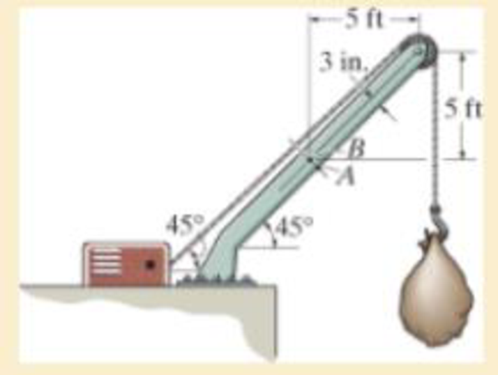
The crane is used to support the 350-lb load. Determine the principal stresses acting in the boom at points A and B. The cross section is rectangular and has a Width of 6 in and a thickness of 3 in. Use Mohr’s circle.
Expert Solution & Answer
Want to see the full answer?
Check out a sample textbook solution
Students have asked these similar questions
Determine the maximum distance d to the edge of the plate at which the force P can be applied so that it produces no compressive stresses on the plate at section a–a. The plate has a thickness of 20 mm and P acts along thecenterline of this thickness.
The box beam is subjected to the 26-kN force that is applied at the center of its width, 75 mm from each side. Determine the principal stresses at point A and show the results in an element located at this point. Use the shear formula to calculate the shear stress.
The hook is subjected to the force of 80 lb. Determine the state of stress at point B at section a–a. The cross section has a diameter of 0.5 in. Use the curved-beam formula to calculate the bending stress.
Chapter 9 Solutions
Mechanics of Materials
Ch. 9.3 - Determine the normal stress and shear stress...Ch. 9.3 - Determine the equivalent state of stress on an...Ch. 9.3 - Also, find the corresponding orientation of the...Ch. 9.3 - Determine the equivalent state of stress on an...Ch. 9.3 - Determine the maximum principal stress at point B.Ch. 9.3 - Determine the principal stress at point C.Ch. 9.3 - Determine the stress components acting on the...Ch. 9.3 - Solve Prob.99 using the stress transformation...Ch. 9.3 - Determine the stress components acting on the...Ch. 9.3 - Determine the equivalent state of stress on an...
Ch. 9.3 - The stress along two planes at a point is...Ch. 9.3 - The state of stress at a point in a member is...Ch. 9.3 - The wood beam is subjected to a load of 12 kN. If...Ch. 9.3 - The internal loadings at a section of the beam are...Ch. 9.3 - Solve Prob.925 for point B. 925. The internal...Ch. 9.3 - Solve Prob.925 for point C. 925. The internal...Ch. 9.3 - It is subjected to a torque of 12 kip in. and a...Ch. 9.3 - A paper tube is formed by rolling a cardboard...Ch. 9.3 - Solve Prob.931 for the normal stress acting...Ch. 9.3 - Determine the principal stresses in the...Ch. 9.3 - The shaft has a diameter d and is subjected to the...Ch. 9.4 - Use Mohrs circle to determine the normal stress...Ch. 9.4 - Also, find the corresponding orientation of the...Ch. 9.4 - Draw Mohrs circle and determine the principal...Ch. 9.4 - Determine the principal stresses at a point on the...Ch. 9.4 - Determine the principal stresses at point A on the...Ch. 9.4 - Point A is just below the flange.Ch. 9.4 - Mohrs circle for the state of stress is shown in...Ch. 9.4 - Determine (a) the principal stresses and (b) the...Ch. 9.4 - Determine the equivalent state of stress if an...Ch. 9.4 - Draw Mohrs circle that describes each of the...Ch. 9.4 - Draw Mohrs circle trial describes each of the...Ch. 9.4 - Determine (a) the principal stresses and (b) the...Ch. 9.4 - Determine (a) the principal stresses and (b) the...Ch. 9.4 - Draw Mohrs circle that describes each of the...Ch. 9.4 - The grains of wood in the board make an angle of...Ch. 9.4 - A spherical pressure vessel has an inner radius of...Ch. 9.4 - The cylindrical pressure vessel has an inner...Ch. 9.4 - If the box wrench is subjected to the 50 lb force,...Ch. 9.4 - If the box wrench is subjected to the 50-lb force,...Ch. 9.5 - Draw the three Mohrs circles that describe each of...Ch. 9.5 - Draw the three Mohrs circles that describe the...Ch. 9.5 - Determine the principal stresses and the absolute...Ch. 9.5 - The solid shaft is subjected to a torque, bending...Ch. 9.5 - The frame is subjected to a horizontal force and...Ch. 9 - Prob. 1RPCh. 9 - The steel pipe has an inner diameter of 2.75 in....Ch. 9 - Determine the equivalent state of stress If an...Ch. 9 - The crane is used to support the 350-lb load....Ch. 9 - Determine the equivalent state of stress on an...Ch. 9 - The propeller shaft of the tugboat is subjected to...Ch. 9 - Determine the principal stresses in the box beam...Ch. 9 - Determine (a) the principal stresses and (b) the...Ch. 9 - Determine the stress components acting on the...
Knowledge Booster


Learn more about
Need a deep-dive on the concept behind this application? Look no further. Learn more about this topic, mechanical-engineering and related others by exploring similar questions and additional content below.Similar questions
- The screw of the clamp exerts a compressive force of 500 lb on the wood blocks. Determine the maximum normal stress along section a–a. The cross section is rectangular, 0.75 in. by 0.50 in.arrow_forwardDetermine the principal stresses in the cantilevered beam at points A and B.arrow_forwardThe wide-flange beam is subjected to the 50-kN force. Determine the principal stresses in the beam at point A located on the web at the bottom of the upper flange. Although it is not very accurate, use the shear formula tocalculate the shear stress.arrow_forward
- The screw of the clamp exerts a compressive force of 500 lb on the woodblocks. Sketch the stress distribution along section a–a of the clamp. The cross section is rectangular, 0.75 in. by 0.50 in.arrow_forwardThe lap joint is fastened by 5 one-inch diameter rivets. For P = 10 kips, determine (1.) the maximum shear stress in the joints, (2.) the maximum bearing stress in the rivets, and (3.) the maximum stress at section a-a.arrow_forwardThe clamp presses the smooth surface at E when tightening the screw. If the tension in the bolt is 40 kN, determine the principal stress at points A and B and show the results on the elements located at each of these points. The cross-sectional area at A and B is shown in the adjacent figure. 300 mm 50 mm 30 mm 100 mm B 25 mm A 100 mm -50 mmarrow_forward
- The plate has a thickness of 20 mm and width s = 260 mm. Force P acts along the centerline of this thickness. Determine the maximum distance d at which the force P can be applied so that it produces no compressive stresses on the plate at section a-a.arrow_forwardThe plate has a thickness of 20 mm and the force P = 3 kN acts along the centerline of this thickness such that d = 150 mm. Plot the distribution of normal stress acting along section a–a.arrow_forward6kN and 1.0KNM loads are applied to the top of the 62-mm-diameter cast-iron as shown. Determine the principal stresses (max and min normal stresses), principal planes (orientation of plane for max-min normal stresses) and max shear stress by using Mohr's circle. Hint: Use given coordinate system. So, H is on x-z plane and K is on y- z plane 1.0 kN.m 6 kN X 220 mmarrow_forward
- Determine the normal stress at corners A and B of the column.arrow_forwardThe horizontal force of P = 80 KN acts at the end of the plate. The plate has a thickness of 10 mm and P acts along the centerline of this thickness such that d = 50 mm. Plot the distribution of normal stress acting along section a-a.arrow_forwardThe vertical force P acts on the bottom of the plate having a negligible weight. Determine the shortest distance d to the edge of the plate at which it can be applied so that it produces no compressive stresses on the plate at section a-a. The plate has a thickness of 10 mm and P acts along the centerline of this thickness. a 200 mm- d 300 mm a 500 mmarrow_forward
arrow_back_ios
SEE MORE QUESTIONS
arrow_forward_ios
Recommended textbooks for you
 Elements Of ElectromagneticsMechanical EngineeringISBN:9780190698614Author:Sadiku, Matthew N. O.Publisher:Oxford University Press
 Mechanics of Materials (10th Edition)Mechanical EngineeringISBN:9780134319650Author:Russell C. HibbelerPublisher:PEARSON
 Thermodynamics: An Engineering ApproachMechanical EngineeringISBN:9781259822674Author:Yunus A. Cengel Dr., Michael A. BolesPublisher:McGraw-Hill Education
 Control Systems EngineeringMechanical EngineeringISBN:9781118170519Author:Norman S. NisePublisher:WILEY
 Mechanics of Materials (MindTap Course List)Mechanical EngineeringISBN:9781337093347Author:Barry J. Goodno, James M. GerePublisher:Cengage Learning
 Engineering Mechanics: StaticsMechanical EngineeringISBN:9781118807330Author:James L. Meriam, L. G. Kraige, J. N. BoltonPublisher:WILEY
Elements Of Electromagnetics
Mechanical Engineering
ISBN:9780190698614
Author:Sadiku, Matthew N. O.
Publisher:Oxford University Press
Mechanics of Materials (10th Edition)
Mechanical Engineering
ISBN:9780134319650
Author:Russell C. Hibbeler
Publisher:PEARSON
Thermodynamics: An Engineering Approach
Mechanical Engineering
ISBN:9781259822674
Author:Yunus A. Cengel Dr., Michael A. Boles
Publisher:McGraw-Hill Education
Control Systems Engineering
Mechanical Engineering
ISBN:9781118170519
Author:Norman S. Nise
Publisher:WILEY
Mechanics of Materials (MindTap Course List)
Mechanical Engineering
ISBN:9781337093347
Author:Barry J. Goodno, James M. Gere
Publisher:Cengage Learning
Engineering Mechanics: Statics
Mechanical Engineering
ISBN:9781118807330
Author:James L. Meriam, L. G. Kraige, J. N. Bolton
Publisher:WILEY
Pressure Vessels Introduction; Author: Engineering and Design Solutions;https://www.youtube.com/watch?v=Z1J97IpFc2k;License: Standard youtube license