
Fundamentals of Electric Circuits
6th Edition
ISBN: 9780078028229
Author: Charles K Alexander, Matthew Sadiku
Publisher: McGraw-Hill Education
expand_more
expand_more
format_list_bulleted
Concept explainers
Videos
Textbook Question
Chapter 8.3, Problem 4PP
The circuit in Fig. 8.12 has reached steady state at t = 0−. If the make-before-break switch moves to position b at t = 0, calculate i(t) for t > 0.
Answer: e−2.5t(10 cos 1.6583t − 15.076 sin 1.6583 t) A.
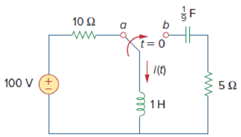
Figure 8.12
For Practice Prob. 8.4.
Expert Solution & Answer
Want to see the full answer?
Check out a sample textbook solution
Students have asked these similar questions
Question 8.
12V
in
R₁
A
R₁
5
V
C
R₂2
w
R₂
4
Consider the circuit below, where the capacitor is uncharged, and the switch is open.
The different elements of the circuit have the following values: R₁ = 22, R₂ = 22, R3 = 422, R₁ = 82, R₁ = 82 and C = 10 µF.
What is the current I₁ in the circuit when the switch is moved to position 1?
Enter your answer, in Amps, in the box below.
The answer is acceptable within a tolerance of 0.1 A.
h₁:
R3
After a long time that the switch has been closed, what is the voltage Vc across the capacitor?
Enter your answer, in Volts, in the box below.
The answer is acceptable within a tolerance of 0.1 V.
Vc:
8.23
At t=0 s, a 100-V source is switched in series with a 1-k resistor and an uncharged 2-µF
capacitor. What are (a) the initial capacitor voltage, (b) the initial current, (c) the initial rate of
capacitor voltage increase, and (d) the time required for the capacitor voltage to reach its
maximum value?
Picture (1) we can see the circuit where L=4mH, C=2uF and Vs is given in picture (2). The question asks the value of İc at t=8ms.
Note: The time (t) given in the graph is in mili seconds (ms)
TIA
Chapter 8 Solutions
Fundamentals of Electric Circuits
Ch. 8.2 - The switch in Fig. 8.4 was open for a long time...Ch. 8.2 - For the circuit in Fig. 8.7, find: (a) iL(0+),...Ch. 8.3 - If R = 10 , L = 5 H, and C = 2 mF in Fig. 8.8,...Ch. 8.3 - The circuit in Fig. 8.12 has reached steady state...Ch. 8.4 - In Fig. 8.13, let R = 2 , L = 0.4 H, C = 25 mF,...Ch. 8.4 - Refer to the circuit in Fig. 8.17. Find v(t) for t...Ch. 8.5 - Having been in position a for a long time, the...Ch. 8.6 - Find i(t) and v(t) for t 0 in the circuit of Fig....Ch. 8.7 - Determine v and i for t 0 in the circuit of Fig....Ch. 8.7 - For t 0, obtain v0(t) in the circuit of Fig....
Ch. 8.8 - In the op amp circuit shown in Fig. 8.34, vs =...Ch. 8.9 - Find i(t) using PSpice for 0 t 4 s if the pulse...Ch. 8.9 - Refer to the circuit in Fig. 8.21 (see Practice...Ch. 8.10 - Draw the dual circuit of the one in Fig. 8.46.Ch. 8.10 - For the circuit in Fig. 8.50, obtain the dual...Ch. 8.11 - In Fig. 8.52, find the capacitor voltage vC for t ...Ch. 8.11 - The output of a D/A converter is shown in Fig....Ch. 8 - For the circuit in Fig. 8.58, the capacitor...Ch. 8 - For Review Questions 8.1 and 8.2. 8.2For the...Ch. 8 - When a step input is applied to a second-order...Ch. 8 - If the roots of the characteristic equation of an...Ch. 8 - In a series RLC circuit, setting R = 0 will...Ch. 8 - Prob. 6RQCh. 8 - Refer to the series RLC circuit in Fig. 8.59. What...Ch. 8 - Consider the parallel RLC circuit in Fig. 8.60....Ch. 8 - Match the circuits in Fig. 8.61 with the following...Ch. 8 - Prob. 10RQCh. 8 - For the circuit in Fig. 8.62, find: (a)i(0+) and...Ch. 8 - Using Fig. 8.63, design a problem to help other...Ch. 8 - Refer to the circuit shown in Fig. 8.64....Ch. 8 - In the circuit of Fig. 8.65, find: (a) v(0+) and...Ch. 8 - Refer to the circuit in Fig. 8.66. Determine: (a)...Ch. 8 - In the circuit of Fig. 8.67, find: (a) vR(0+) and...Ch. 8 - A series RLC circuit has R = 20 k, L = 0.2 mH, and...Ch. 8 - Design a problem to help other students better...Ch. 8 - The current in an RLC circuit is described by...Ch. 8 - The differential equation that describes the...Ch. 8 - Prob. 11PCh. 8 - If R = 50 , L = 1.5 H, what value of C will make...Ch. 8 - For the circuit in Fig. 8.68, calculate the value...Ch. 8 - The switch in Fig. 8.69 moves from position A to...Ch. 8 - The responses of a series RLC circuit are...Ch. 8 - Find i(t) for t 0 in the circuit of Fig. 8.70....Ch. 8 - In the circuit of Fig. 8.71, the switch...Ch. 8 - Find the voltage across the capacitor as a...Ch. 8 - Obtain v(t) for t 0 in the circuit of Fig. 8.73....Ch. 8 - The switch in the circuit of Fig. 8.74 has been...Ch. 8 - Calculate v(t) for t 0 in the circuit of Fig....Ch. 8 - Assuming R = 2 k, design a parallel RLC circuit...Ch. 8 - For the network in Fig. 8.76, what value of C is...Ch. 8 - The switch in Fig. 8.77 moves from position A to...Ch. 8 - Using Fig. 8.78, design a problem to help other...Ch. 8 - The step response of an RLC circuit is given by...Ch. 8 - Prob. 27PCh. 8 - A series RLC circuit is described by...Ch. 8 - Solve the following differential equations subject...Ch. 8 - Prob. 30PCh. 8 - Consider the circuit in Fig. 8.79. Find vL(0+) and...Ch. 8 - For the circuit in Fig. 8.80, find v(t) for t 0.Ch. 8 - Find v(t) for t 0 in the circuit of Fig. 8.81.Ch. 8 - Calculate i(t) for t 0 in the circuit of Fig....Ch. 8 - Using Fig. 8.83, design a problem to help other...Ch. 8 - Obtain v(t) and i(t) for t 0 in the circuit of...Ch. 8 - For the network in Fig. 8.85, solve for i(t) for t...Ch. 8 - Refer to the circuit in Fig. 8.86. Calculate i(t)...Ch. 8 - Determine v(t) for t 0 in the circuit of Fig....Ch. 8 - The switch in the circuit of Fig. 8.88 is moved...Ch. 8 - For the network in Fig. 8.89, find i(t) for t 0....Ch. 8 - Given the network in Fig. 8.90, find v(t) for t ...Ch. 8 - The switch in Fig. 8.91 is opened at t = 0 after...Ch. 8 - A series RLC circuit has the following parameters:...Ch. 8 - In the circuit of Fig. 8.92, find v(t) and i(t)...Ch. 8 - Prob. 46PCh. 8 - Find the output voltage vo(t) in the circuit of...Ch. 8 - Given the circuit in Fig. 8.95, find i(t) and v(t)...Ch. 8 - Determine i(t) for t 0 in the circuit of Fig....Ch. 8 - For the circuit in Fig. 8.97, find i(t) for t 0....Ch. 8 - Find v(t) for t 0 in the circuit of Fig. 8.98....Ch. 8 - The step response of a parallel RLC circuit is...Ch. 8 - After being open for a day, the switch in the...Ch. 8 - Using Fig. 8.100, design a problem to help other...Ch. 8 - For the circuit in Fig. 8.101, find v(t) for t 0....Ch. 8 - In the circuit of Fig. 8.102, find i(t) for t 0....Ch. 8 - Given the circuit shown in Fig. 8.103, determine...Ch. 8 - In the circuit of Fig. 8.104, the switch has been...Ch. 8 - The switch in Fig. 8.105 has been in position 1...Ch. 8 - Obtain i1 and i2 for t 0 in the circuit of Fig....Ch. 8 - For the circuit in Prob. 8.5, find i and v for t ...Ch. 8 - Find the response vR(t) for t 0 in the circuit of...Ch. 8 - For the op amp circuit in Fig. 8.108, find the...Ch. 8 - Using Fig. 8.109, design a problem to help other...Ch. 8 - Determine the differential equation for the op amp...Ch. 8 - Obtain the differential equations for vo(t) in the...Ch. 8 - In the op amp circuit of Fig. 8.112, determine...Ch. 8 - For the step function vs = u(t), use PSpice or...Ch. 8 - Given the source-free circuit in Fig. 8.114, use...Ch. 8 - For the circuit in Fig. 8.115, use PSpice or...Ch. 8 - Obtain v(t) for 0 t 4 s in the circuit of Fig....Ch. 8 - The switch in Fig. 8.117 has been in position 1...Ch. 8 - Design a problem, to be solved using PSpice or...Ch. 8 - Draw the dual of the circuit shown in Fig. 8.118.Ch. 8 - Obtain the dual of the circuit in Fig. 8.119.Ch. 8 - Find the dual of the circuii in Fig. 8.120.Ch. 8 - Draw the dual of the circuit in Fig. 8.121.Ch. 8 - An automobile airbag igniter is modeled by the...Ch. 8 - A load is modeled as a 100-mH inductor in parallel...Ch. 8 - A mechanical system is modeled by a series RLC...Ch. 8 - An oscillogram can be adequately modeled by a...Ch. 8 - The circuit in Fig. 8.123 is the electrical analog...Ch. 8 - Figure 8.124 shows a typical tunnel-diode...
Knowledge Booster


Learn more about
Need a deep-dive on the concept behind this application? Look no further. Learn more about this topic, electrical-engineering and related others by exploring similar questions and additional content below.Similar questions
- Lesson= Second Order Transient Response A 24-V battery is connected in seires with a 1-Henry (inductor), 8-ohms resistor and a 1/16 Farad ( capacitor) with when the switchis turned “on” at t = 0. And then, what will be the value of the current at t = 0.001 sec.arrow_forward8a. R1 2k0 Hilt Use the differential equation approach to find v (t) for t> 0 in the circuit in Figure 8. Show all V1 10V R2 www 4k0 R5 ww 3k0 switch closes at 1-0 R3 1k0 C1 HH 100μF V2 5V a R4 34k0 vo(t)arrow_forward8a. Use the differential equation approach to find v (t) for t> 0 in the circuit in Figure 8. Show all work neatly Circle your final answer. R1 2k0 V1 10V R2 www 4k0 R5 www 3k0 switch closes at 1-0 R3 ww 1k0 C1 HH 100μF V2 =5V -0 R4 34k0 vo(t)arrow_forward
- (b) The voltage across a 4 N resistor of an RC circuit in Figure Q8(b) is given by VR (t) = 2e-6tu(t)V. Determine the total energy dissipated by this resistor using Parseval's Theorem. R C Figure Q8(b)arrow_forwardAn electric circuit contains an 8 ohm resistor in series with an inductor of 0.50 henries and a battery of E volts. At t=0 the current is zero. Find the current at any time t > 0 and the maximum current if (a) E=64, (b) E=8te-16t, (c) E=32e-8t, (d) E = 64sin8tarrow_forwardGENERAL RLC CIRCUITS: Solve and show your solution completely. Make sure your answers are in 4 decimals places. A 400 mH coil of negligible resistance is connected to an AC circuit in which an effectivecurrent of 6 mA is flowing. Find out the voltage across the coil if the frequency is 1000 Hz.arrow_forward
- 2. Eudora is observing a certain circuit consists of an inductance of 0.0s henry having a resistance of 20 ohm. Alse a condenser record a capacitance of 100 microfarads with a voltage supply of 100 cos200t V. Find the equation for q and i at steady state conditionarrow_forwardConsider the circuit in the following figure. Under dc conditions, find: (a) i, gc, and is. (b) the energy stored in the capacitor and inductor. 12 V 192 wwww "C 492 1 F 592 2 H ell ILarrow_forwardP 8:11 A docs.google.com 36% O ASIACELL lI. 3. Determine the kind of damping and the value of q for the arrow refers to number #1 in the figure below 1 0.8 0.6 옷 0.4 0.2 -0.2 6. 8 10 time(s) A. Overdamping, q equal to zero B. Underdamping, q equal to zero C. Critical damping, q equal to zero D. Overdamping, q more than zero E. Underdamping, q more than zero F. Critical damping, q more than zero G. Overdamping, q less than zero H. Underdamping, q less than zero Critical damping, q less than zero I. O A В D Earrow_forward
- For the circuit in Figure 3 the switch is in the left position for several minutes: (a) Find the Initlal voltage, V, on the capacitor just before the switch is flipped (b) Find an expression v(t) that describes the voltage across the 20 N resistor after the switch has been Figure 3 U 09 flipped to the right NOTE: Remember what we said in class: use a Circuit-Specific Equation to get a value you know. Then solve for whatever else the problem asks for +50 µF 380 0 20 2arrow_forwardA circuit containing a 10 Ohms resistance is in series to 250 microFarad capacitance with a source of 40Volts. The switch is turned on at t = 0. What is the time will reach the the steady state value?arrow_forward8.7 Find the voltage v, in the circuit of Figure P8.7. 12 k2 ww- 2 ΚΩ 6 kΩ ww ww- 11 V 4 k2 wwarrow_forward
arrow_back_ios
SEE MORE QUESTIONS
arrow_forward_ios
Recommended textbooks for you
 Introductory Circuit Analysis (13th Edition)Electrical EngineeringISBN:9780133923605Author:Robert L. BoylestadPublisher:PEARSON
 Delmar's Standard Textbook Of ElectricityElectrical EngineeringISBN:9781337900348Author:Stephen L. HermanPublisher:Cengage Learning
 Programmable Logic ControllersElectrical EngineeringISBN:9780073373843Author:Frank D. PetruzellaPublisher:McGraw-Hill Education
 Fundamentals of Electric CircuitsElectrical EngineeringISBN:9780078028229Author:Charles K Alexander, Matthew SadikuPublisher:McGraw-Hill Education
 Electric Circuits. (11th Edition)Electrical EngineeringISBN:9780134746968Author:James W. Nilsson, Susan RiedelPublisher:PEARSON
 Engineering ElectromagneticsElectrical EngineeringISBN:9780078028151Author:Hayt, William H. (william Hart), Jr, BUCK, John A.Publisher:Mcgraw-hill Education,
Introductory Circuit Analysis (13th Edition)
Electrical Engineering
ISBN:9780133923605
Author:Robert L. Boylestad
Publisher:PEARSON
Delmar's Standard Textbook Of Electricity
Electrical Engineering
ISBN:9781337900348
Author:Stephen L. Herman
Publisher:Cengage Learning
Programmable Logic Controllers
Electrical Engineering
ISBN:9780073373843
Author:Frank D. Petruzella
Publisher:McGraw-Hill Education
Fundamentals of Electric Circuits
Electrical Engineering
ISBN:9780078028229
Author:Charles K Alexander, Matthew Sadiku
Publisher:McGraw-Hill Education
Electric Circuits. (11th Edition)
Electrical Engineering
ISBN:9780134746968
Author:James W. Nilsson, Susan Riedel
Publisher:PEARSON
Engineering Electromagnetics
Electrical Engineering
ISBN:9780078028151
Author:Hayt, William H. (william Hart), Jr, BUCK, John A.
Publisher:Mcgraw-hill Education,
ENA 9.2(1)(En)(Alex) Sinusoids & Phasors - Explanation with Example 9.1 ,9.2 & PP 9.2; Author: Electrical Engineering Academy;https://www.youtube.com/watch?v=vX_LLNl-ZpU;License: Standard YouTube License, CC-BY
Electrical Engineering: Ch 10 Alternating Voltages & Phasors (8 of 82) What is a Phasor?; Author: Michel van Biezen;https://www.youtube.com/watch?v=2I1tF3ixNg0;License: Standard Youtube License