
Videos
6.70 through 6.74 classify as determinate or indeterminate. (All members act both in tension and in compression.)
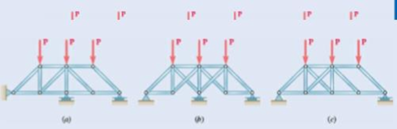
Fig. P6.73
Structure (a):
Rigid truss with r = 3, m = 14, n = 8,
so r + m = 17 > 2n = 16
so completely constrained but indeterminate
Structure (b): Simple truss (start with ABC and add joints alphabetically), with
r = 3, m = 13, n = 8, so r + m = 16 = 2n
so completely constrained and determinate
Structure (c):
Simple truss with r = 3, m = 13, n = 8, so r + m = 16 = 2n, hut horizontal reactions (Ax and Dx) are collinear, so cannot he resolved by any equilibrium equation.
Structure is improperly constrained.
Want to see the full answer?
Check out a sample textbook solution
Chapter 6 Solutions
Vector Mechanics for Engineers: Statics and Dynamics
Additional Engineering Textbook Solutions
Shigley's Mechanical Engineering Design (McGraw-Hill Series in Mechanical Engineering)
Fundamentals Of Thermodynamics
Manufacturing Engineering & Technology
Introduction to Heat Transfer
Thinking Like an Engineer: An Active Learning Approach (3rd Edition)
Applied Fluid Mechanics (7th Edition)


- Activity 1. For the truss shown in the figure, determine the forces acting on members AB, AC,BC,CE by method of joints.[Ans. AB=247.88KN(C), BC=50KN(T), CE=AC=206.25KN(T)] 100 N 50N 50 N 2m H 1.5m C 1.5m E 1.5m G 50N Activity 2. Solve for the force acting on members AB, AC and BC of the Warren Truss shown using method of joint. [Ans. AB=672KN(T), AC=300KN(C), BC=672KN(C)] 400 KN 300 KN D+ 6m 6m 6m 6m 600KN 200 KNarrow_forwardCalculate the support reactions for the truss below. W = 4,4 kNh = 12,4 marrow_forwardA new art exhibit featuring mobile works is going up in the Norwalk, CA area. One art work is shown in the figure below. A 105 N uniform beam is pinned to the ground by a pivot. The beam is supported by a cable (attached 3/5 from the bottom of the beam) to allow for each of the shoes to hang freely. Each individual shoe has a weight of 7.5 N. 10 WALL FLOR (a) ( If one shoe is attached 1/7 of the way up the beam and another shoe is attached 5/8 of the way up the beam, with e, = 70.1° and e, 30.1°, what is the tension in the cable, in newtons? %3! %3D (b) What is the x-component of the force, in newtons, that the pivot exerts on the bottom of the beam? (c) O What is the y-component of the force, in newtons, that the pivot exerts on the bottom of the beam?arrow_forward
- 5.3.4 Zero Force Members Figure H 800 N ALA F E MA 3m D -3 m 30% G B -3 m 20 1 of 2 ( 3m Figure B 2m 2 m C T 2 m < 2 of 2 D 4m 500 N 700 N Part A Identify the zero-force members in the truss shown in (Figure 1). Check all that apply. CD D BC D CE ⒸAB DE GH EF ооооооооооооо BG □ CF AG OBF FG ⒸAH Part B Identify the zero-force members in the truss shown in (Figure 2). Check all that apply. OBC FG D CF AG BG OCD DE ⒸAB D CG EF ODF оооооооооооarrow_forwardActivity 1. For the truss shown in the figure, determine the forces acting on members AB, AC,BC,CE by method of joints.[Ans. AB=247.88KN(C), BC=50KN(T), CE=AC=206.25KN(T)] 100 N D. 50N 50 N B. F 2m 1.5m |C 1.5m E 1.5m G 50Narrow_forward5. Analyze the following trusses using the finite element method if E = 200GPA and area of cross section A = 2cm? for all members. 1m 1m 1m 1m 1.5m 1m P=50 kN P1=30 kN P2=65 kN (a) (b) Fig. P3.3arrow_forward
- 3) Calculate the internal forces in members DF, CE, and BD of the given truss shown in the figure below. Use the Method of Sections. G0ON GOON GOON GOON G0ON 1,5m 600 N B. 600 N A 6 at 1-20m = 7.20marrow_forwardA new art exhibit featuring mobile works is going up in the Holland, MI, area. One piece is shown in the figure. The 155-N uniform beam is pinned to the ground by a pivot. The beam is supported by a cable (attached to the center of the beam) to allow for each of the shoes to hang freely. Each individual shoe has a weight of 9.5-N. If one shoe is attached two-fifths of the way up the beam and another shoe is attached and three-fifths of the way up the beam, with θc = 16.5° and θb = 33.6° as shown in the figure, what is the tension in the cable, in newtons? What is the x-component of the force, in newtons, that the pivot exerts on the bottom of the beam? Use the coordinate system specified in the figure. What is the y-component of the force, in newtons, that the hinge exerts on the bottom of the beam? Use the coordinate system specified in the figure.arrow_forwardA simply supported span (middle span) of 6-m length with double cantilever of 1.5 m at each end is loaded as shown below. There is a concentrated moment of 6 kN-m acting at the tip of the left cantilever and a point load of 3 kN acting at the tip of the right cantilever. A concentrated force P = 10 kN is acting at the mid-point of the middle span. In addition, there are two partial uniform load of 5 kN/m acting on the middle span as shown below. The middle span has an I-section, of which the value of the moment of inertia I is given. The dimensions of the two flanges and the vertical web are also given. The right cantilever has a T-section. The dimensions of the top flange and the web are given. a).Calculate the maximum bending stress of the middle span and plot the bending stress distribution. The middle span is an I-section and the value of moment of inertia I is given as shown above b.) Calculate the maximum shear stress of the middle span and the shear stress at the interface…arrow_forward
- 00 %24 Week4 Frames1 21-22-1 (1).pdf File C/Users/callu/Downloads/Week4 Frames1 21-22-1%20(1).pdf T Add text Draw E Highlight 2 Erase (D Page view IA Read aloud 5. Determine the support forces and force in each member of the truss in Fig. Q5 and state if the members are in tension or compression. 3 kN 1.5 m o0E = 0 B. 2 m 2 m 4 kN Fig. Q5 a) Draw FBD of truss ABCD and determine support forces at A and C. b) Draw FBD of pin at C. Determine unknown member forces. c) Draw FBD of pin at B. Determine unknown member forces. d) Draw FBD of pin at A. Determine unknown member force. [A,=1.2kN, A,=0.88KN, C,=1.8kN, C,=3.13KN, FBC= 2.37(T), FCD= 5.21(C), FAR 2.37(T), Fan= 4.0(T), FAD= 1.47(C)] %3D 14:56 12°C Raining now 31/10/2021 6. 五 O e A DO BANG &OL 12 61 delete home 144 pua I14 dn pd num 2. + backspace lock * 4. 5. 3. R { %#3 home 7. 4. prt scarrow_forwardFor the truss shown in figure, determine the forces in elements BD and CD, state whether each member is in tension or compression. 20 ft 20 ft 20 ft 260 lb 300 lb 300 lb 260 lb 25 ft B A E 30 ft 30 ft Equations E#2.pdf CD = 469 (T), BD 2305 (C) CD = 323 (T), BD = 679 (C) CD -233 (T), BD = 520 (C) !3!arrow_forwardPROBLEM NO. 2 A 12kN AND 50KN WEIGHTS ARE ATTACTHED TO THE CANTILEVER BEAM IN THE FIGURE BELOW CALCULATE THE TENSION OF THE CABLE IF THE PULLEY IS FRICTIONLESS, CALCULATE THE REACTION AT POINT A. 3. B 1.5 0.5 0.5 14 kN) 50 kNarrow_forward
 Elements Of ElectromagneticsMechanical EngineeringISBN:9780190698614Author:Sadiku, Matthew N. O.Publisher:Oxford University Press
 Mechanics of Materials (10th Edition)Mechanical EngineeringISBN:9780134319650Author:Russell C. HibbelerPublisher:PEARSON
 Thermodynamics: An Engineering ApproachMechanical EngineeringISBN:9781259822674Author:Yunus A. Cengel Dr., Michael A. BolesPublisher:McGraw-Hill Education
 Control Systems EngineeringMechanical EngineeringISBN:9781118170519Author:Norman S. NisePublisher:WILEY
 Mechanics of Materials (MindTap Course List)Mechanical EngineeringISBN:9781337093347Author:Barry J. Goodno, James M. GerePublisher:Cengage Learning
 Engineering Mechanics: StaticsMechanical EngineeringISBN:9781118807330Author:James L. Meriam, L. G. Kraige, J. N. BoltonPublisher:WILEY