
Concept explainers
Videos
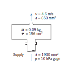
A spray system is shown in the diagram. Water is supplied at p = 10 kPa gage, through the flanged opening of area A = 1900 mm2. The water leaves in a steady free jet at atmospheric pressure. The jet area and speed are A = 650 mm2 and V = 4.6 m/s. The mass of the spray system is 0.09 kg and it contains V = 196 cm3 of water.
P6.57
An object, with a flat horizontal lower surface, moves downward into the jet of the spray system with speed U = 5 ft/s. Determine the minimum supply pressure needed to produce the jet leaving the spray system at V = 15 ft/s. Calculate the maximum pressure exerted by the liquid jet on the flat object at the instant when the object is h = 1.5 ft above the jet exit. Estimate the force of the water jet on the flat object.
Want to see the full answer?
Check out a sample textbook solution
Chapter 6 Solutions
Fox and McDonald's Introduction to Fluid Mechanics
Additional Engineering Textbook Solutions
Mechanics of Materials (10th Edition)
Automotive Technology: Principles, Diagnosis, And Service (6th Edition) (halderman Automotive Series)
Heating Ventilating and Air Conditioning: Analysis and Design
Fundamentals of Heat and Mass Transfer
Mechanics of Materials
Automotive Technology: Principles, Diagnosis, and Service (5th Edition)


- Water in a vertical (i.e., gravitational force of the fluid in the nozzle plays a role, and the elevation change in the Bernoulli's Equation, if needed, should be considered) pipe is charging from an attached bend nozzle into the atmosphere as shown in Fig. 5. The nozzle's weight is 20 kg. The pipe and the nozzle are connected by a flange. The gage pressure of the flow at the flange is 35 kPa when the discharge rate is 0.1 m³/s. The volume of the bending nozzle is 0.012 m³. Calculate the vertical component of the anchoring forcing required to hold the nozzle in place and determine its direction. G= 9.81 m/s². The density of water is 1000 kg/m³. ChatGPT solution: Nozzle 1 Area -0.01 m² P-35 kPa Area -0.025 m² 0.10 ms Figure 5: Q5 35 degreearrow_forwardQ1. Converging duct at steady one dimensional flow, Inlet section: p = 2.35 kg-m³, A = 0.59 m², v = 41 m-s1, Exit section: p = 1.96 kg-m, A = 0.09 m². Find exit velocity. Q2. Gas turbine engine, m°, Section 1: A =0.46 m?, v = 259 m-s1, T = 303 K, p= 72 kPa Section 2: A =0.41 m?, v = 251 m-s1, T = 305 K, p= 70 kPa m°p = 0.247 m°1, find m°? Q3: Diverging channel, Section 1: A =0.73 m?, v = 7.7 m-s1, p = 1.23 kg-m3 Section 2: A =1.24 m?, v = 2.7 m-s1, p = 1.41 kg-m3 1. Determine the flow is compressible or not? 2. Determine the flow is steady or not? Q4: Air in rigid tank at volume = 0.73 m³, p = 485 kPa, T = 40 C°. A hole in the tank has 89 mm?, velocity of air from it = 355 m-s1. Determine the rate of change of density?arrow_forwardProblem 4: Find the maximum power developed by the turbine. Data: H1 = 37 m, H4 = 2 m, D2 = 56 cm, D4 = 35 cm, V4 = 8.5 m/s, P4 = 200 kPa, Patm = 100 kPa, p = 1000 kg/m3. Lake |H, V4 4 H, Turbinearrow_forward
- While rotating at 900 rpm, a centrifugal pump delivers 2500 gpm of water at ahead of 75 ft. If the impeller diameter is 1.5 ft. and the blade width is 1.75 in.,find the (a) blade angle β2, (b) radial velocity Vr2, and (c) blade speed u2. Assumeno whirl at the inlet.Ans: β2=12.5°; Vr2=8.1 ft./s; u2=70.7 ft./sarrow_forwardA jet of water strikes a splitter and splits into two streams of equal velocity but unequal thickness. All jets have a width w (into the paper). Friction forces of the water stream on the splitter are negligible. Ignore the weight of the splitter. a) Use the integral mass conservation equation to find an equation for the thickness t of angled exit stream, t = f (h, a) b) Apply the momentum equation in the vertical direction to find an equation 0 = f(a).Hint: the net vertical force on the splitter is zero c) Find an equation Fx = f(p, V, w,h,a,0) for the horizontal force on the splitterarrow_forward3. Water flows radially outward through a space between 2 disks of diameter D= 200 mm at a mass flow rate of 365 g/s. The perimeter of the disks is open to the atmosphere and the spacing between them is 0.75 mm. Find the static pressure between the disks at radius, r= 50 mm. %3Darrow_forward
- Q6. A single acting reciprocating pump has a plunger diameter of 10 cm and the stroke of 20 cm. The centre of the pump is 4'm above the water level in the sump and 14 m below the water level in the upper tank. The diameter and the length of suction pipe are 4 cm and 6 m respectively, while that of the delivery are 3 cm and 18 m. Find the maximum speed at which the pump may be run without separation, if the separation occurs at 7.85 N/cm² below the atmospheric pressure i.e. 10.3 m of water.arrow_forwardThe An impeller rotating at 1200 r.p.m. with the following dimensions (b, = 1.5 in., b₂ = 1.0 in., D, 5 in., D₂ = 15 in., ₁= 15°, B₂= 20°, b, and b, are the passage widths at the inlet and outlet with cross-section area A = πDb). impeller develops an actual head of 80 ft and delivers 1000 gpm at the point of maximum efficiency requiring 30 b. hp. Assuming radial inlet flow and neglecting vane thickness. a) draw the virtual velocity diagrams at the inlet and outlet and evaluate all the velocities and angles. virtual head neglecting the circulatory flow c) overall pumn efficiency b)arrow_forwardProb. 3: A steady push on the piston in Fig. causes a flow rate Q = 0.15 cm/s through the needle. The fluid has p = 900 kg/m and u = 0.002 kg/(m-s). What force F is required to maintain the flow? D2 =1 cm D, = 0.25 mm 1.5 cm 3 cmarrow_forward
- A large commercial power washer delivers 21 gal/min ofwater through a nozzle of exit diameter one-third of aninch. Estimate the force of the water jet on a wall normal tothe jet.arrow_forwardThree pipes steadily deliver water at 20°C to a large exit pipe in Fig. The velocity V3 = 8 m/s, and the exit flow rate Q4 = 150 m/h. Find (a) V1; (b) V2; and (c) V4 if it is known that increasing Q2 by 10% would increase Q4 by 5%. D, = 6 cm D; = 5 cm D =9 cm D, = 4 cmarrow_forwardA 20°C water jet strikes a vane on a tank with frictionless wheels, as shown. The jet turns and falls into the tank without spilling. If 0 = 30°, estimate the horizontal force F needed to hold the tank stationary.arrow_forward
 Elements Of ElectromagneticsMechanical EngineeringISBN:9780190698614Author:Sadiku, Matthew N. O.Publisher:Oxford University Press
 Mechanics of Materials (10th Edition)Mechanical EngineeringISBN:9780134319650Author:Russell C. HibbelerPublisher:PEARSON
 Thermodynamics: An Engineering ApproachMechanical EngineeringISBN:9781259822674Author:Yunus A. Cengel Dr., Michael A. BolesPublisher:McGraw-Hill Education
 Control Systems EngineeringMechanical EngineeringISBN:9781118170519Author:Norman S. NisePublisher:WILEY
 Mechanics of Materials (MindTap Course List)Mechanical EngineeringISBN:9781337093347Author:Barry J. Goodno, James M. GerePublisher:Cengage Learning
 Engineering Mechanics: StaticsMechanical EngineeringISBN:9781118807330Author:James L. Meriam, L. G. Kraige, J. N. BoltonPublisher:WILEY