
Mechanics of Materials
9th Edition
ISBN: 9780133254426
Author: Russell C. Hibbeler
Publisher: Prentice Hall
expand_more
expand_more
format_list_bulleted
Videos
Textbook Question
Chapter 5.4, Problem 5.48P
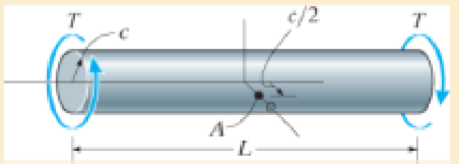
Show that the maximum shear strain in the shaft is γmax = Tc/JG. What is the shear strain on an element located at point A, c/2 from the center of the shaft? Sketch the shear strain distortion of this element.
Expert Solution & Answer
Want to see the full answer?
Check out a sample textbook solution
Students have asked these similar questions
Two fully loaded tractor trailers travel over the bridge putting substantial loading on the structure. As they pass over the middle of the bridge, one of the vertical supporting pillars, which is fixed at its bottom, deforms as shown below. The weight of the trucks causes point T to move to point T'—a distance of 2.5 cm
along the x-axis. If the pillar has an original height of 27 m
, find the shear strain at point T.
2mm
The piece of plastic is originally rectangular.
Suppose that a = 300mm and b =
420 mm
2mm
5mm
TIC
300mm = a
1
Blac
b
1
d
A
B
1
1
1
1
1
1
= 420mm 3mm
14mm
2mm
У
Determine the shear strain rxy at corner B
if the plastic distorts as shown by the
dashed lines.
A stress element in a rock mass making up a slope experiences a 2D stress as follows:
σx = 8 MPa, σy = 4 MPa , tauxy = 3 MPa
A. By using the stress transformation equation, draw a curve of the stress variation experienced by the stress element at the axis of rotation angle θ = 0-180°. Use the interval θ = 1°, with the x-axis and stress as the y-axis. Mark on the curve where the principal stress and maximum shear stress occur. Draw the three stress curves completely and neatly
B. Draw the stress element along with the magnitude and direction of the stress at the angle where the principal stress occurs and at the angle where the maximum shear stress occurs.
C. Write down the direction vectors of the orientation of the principal stress (n1, and n₂) and the maximum shear stress (nmax). Write it in unit vector form i and j.
D. Prove that the value of the stress invariant (I1, and I2) using the principal stress is reached and prove that the orthogonality condition of the direction cosine is…
Chapter 5 Solutions
Mechanics of Materials
Ch. 5.3 - Determine the internal torque at each section and...Ch. 5.3 - Determine the. internal torque at each section and...Ch. 5.3 - The solid and hollow shafts are each subjected to...Ch. 5.3 - The motor delivers 10 hp to the shaft. If it...Ch. 5.3 - The solid circular shaft is subjected to an...Ch. 5.3 - The hollow circular shaft is subjected to an...Ch. 5.3 - The shaft is hollow from A to B and solid from B...Ch. 5.3 - Determine the maximum shear stress in the...Ch. 5.3 - Determine the maximum shear stress in the shaft at...Ch. 5.3 - Determine the shear stress a: point A on the...
Ch. 5.3 - The solid 50-mm-diameter shaft is subjected to the...Ch. 5.3 - The gear motor can develop 3 hp when it turns at...Ch. 5.3 - The solid shaft of radius r is subjected to a...Ch. 5.3 - The solid shaft of radius r is subjected to a...Ch. 5.3 - 5-3. The solid shaft is fixed to the support at C...Ch. 5.3 - The copper pipe has an outer diameter of 40 mm and...Ch. 5.3 - The copper pipe has an outer diameter of 2.50 in....Ch. 5.3 - Prob. 5.6PCh. 5.3 - Prob. 5.7PCh. 5.3 - The solid 30-mm-diameter shaft is used to transmit...Ch. 5.3 - The solid shaft is fixed to the support at C and...Ch. 5.3 - Prob. 5.10PCh. 5.3 - The assembly consists of two sections of...Ch. 5.3 - Prob. 5.12PCh. 5.3 - 5-13. If The tubular shaft is made from material...Ch. 5.3 - A steel tube having an outer diameter of 2.5 in....Ch. 5.3 - Prob. 5.15PCh. 5.3 - Prob. 5.16PCh. 5.3 - The rod has a diameter of 1 in. and a weight of 10...Ch. 5.3 - The rod has a diameter of 1 in. and a weight of 15...Ch. 5.3 - 5-19. The shaft consists of solid 80-mm-diameter...Ch. 5.3 - Prob. 5.20PCh. 5.3 - 5-21. If the 40-mm-diameter rod is subjected to a...Ch. 5.3 - Prob. 5.22PCh. 5.3 - Prob. 5.23PCh. 5.3 - Prob. 5.24PCh. 5.3 - Prob. 5.25PCh. 5.3 - Prob. 5.26PCh. 5.3 - Prob. 5.27PCh. 5.3 - Prob. 5.28PCh. 5.3 - Prob. 5.29PCh. 5.3 - Prob. 5.30PCh. 5.3 - The solid steel shaft AC has a diameter of 25 mm...Ch. 5.3 - The pump operates using the motor that has a power...Ch. 5.3 - Prob. 5.33PCh. 5.3 - Prob. 5.34PCh. 5.3 - Prob. 5.35PCh. 5.3 - Prob. 5.36PCh. 5.3 - Prob. 5.37PCh. 5.3 - Prob. 5.38PCh. 5.3 - Prob. 5.39PCh. 5.3 - Prob. 5.40PCh. 5.3 - The A-36 steel tubular shaft is 2 m long and has...Ch. 5.3 - Prob. 5.42PCh. 5.3 - The solid shaft has a linear taper from rA at one...Ch. 5.3 - *5-44. The rod has a diameter of 0.5 in. and...Ch. 5.3 - 5-45. Solve Prob. 5-44 for the maximum torsional...Ch. 5.3 - A motor delivers 500 hp to the shaft, which is...Ch. 5.4 - The 60 mm-diameter steel shaft is subjected to the...Ch. 5.4 - Prob. 5.10FPCh. 5.4 - The hollow 6061-T6 aluminum shaft has an outer and...Ch. 5.4 - A series of gears are mounted on the...Ch. 5.4 - The 80-mm-diameter shaft is made of steel. If it...Ch. 5.4 - The 80-mm-diameter shaft is made of steel. If it...Ch. 5.4 - The propellers of a ship are connected to an A-36...Ch. 5.4 - Show that the maximum shear strain in the shaft is...Ch. 5.4 - 5-49. The A-36 steel axle is made from tubes AB...Ch. 5.4 - Prob. 5.50PCh. 5.4 - Determine the maximum allowable torque T. Also,...Ch. 5.4 - If the allowable shear stress is allow = 80 MPa,...Ch. 5.4 - Prob. 5.53PCh. 5.4 - If gear B supplies 15 kW of power, while gears A,...Ch. 5.4 - If the shaft is made of steel with the allowable...Ch. 5.4 - *5-56. The A-36 steel axle is made from tubes AB...Ch. 5.4 - If the rotation of the 100-mm-diameter A-36 steel...Ch. 5.4 - If the rotation of the 100-mm-diameter A-36 steel...Ch. 5.4 - It has a diameter of 1 in. and is supported by...Ch. 5.4 - Prob. 5.60PCh. 5.4 - Prob. 5.61PCh. 5.4 - Prob. 5.62PCh. 5.4 - Prob. 5.63PCh. 5.4 - Prob. 5.64PCh. 5.4 - Prob. 5.65PCh. 5.4 - When it is rotating at 80 rad/s. it transmits 32...Ch. 5.4 - It is required to transmit 35 kW of power from the...Ch. 5.4 - Prob. 5.68PCh. 5.4 - If a torque of T = 50 N m is applied to the bolt...Ch. 5.4 - If a torque of T= 50N m is applied to the bolt...Ch. 5.4 - Prob. 5.72PCh. 5.4 - If the shaft is subjected to a torque T at its...Ch. 5.4 - Prob. 5.74PCh. 5.4 - Prob. 5.75PCh. 5.4 - *5-76. A cylindrical spring consists of a rubber...Ch. 5.5 - Gst = 75 GPa.Ch. 5.5 - The A992 steel shaft has a diameter of 60 mm and...Ch. 5.5 - If the shaft is fixed at its ends A and B and...Ch. 5.5 - Prob. 5.80PCh. 5.5 - Prob. 5.81PCh. 5.5 - 5-82. The shaft is made from a solid steel section...Ch. 5.5 - 5-83. The motor A develops a torque at gear B of...Ch. 5.5 - If the allowable shear stresses for the magnesium...Ch. 5.5 - If a torque of T = 5 kNm is applied to end A,...Ch. 5.5 - Each has a diameter of 25 mm and they are...Ch. 5.5 - Each has a diameter of 25 mm and they are...Ch. 5.5 - It is fixed at its ends and subjected to a torque...Ch. 5.5 - 5–89. Determine the absolute maximum shear stress...Ch. 5.5 - The shaft is subjected to a torque of 800 lbft....Ch. 5.5 - Prob. 5.91PCh. 5.5 - The shaft is made of 2014-T6 aluminum alloy and is...Ch. 5.5 - The tapered shaft is confined by the fixed...Ch. 5.5 - Determine the reactions at the fixed supports A...Ch. 5.7 - 5-95. The aluminum rod has a square cross section...Ch. 5.7 - Prob. 5.96PCh. 5.7 - Prob. 5.97PCh. 5.7 - If it is subjected to the torsional loading,...Ch. 5.7 - Solve Prob.5-98 for the maximum shear stress...Ch. 5.7 - determine the maximum shear stress in the shaft....Ch. 5.7 - If the shaft has an equilateral triangle cross...Ch. 5.7 - 5-102. The aluminum strut is fixed between the two...Ch. 5.7 - is applied to the tube If the wall thickness is...Ch. 5.7 - If it is 2 m long, determine the maximum shear...Ch. 5.7 - Also, find the angle of twist of end B. The shaft...Ch. 5.7 - Also, find the corresponding angle of twist at end...Ch. 5.7 - If the solid shaft is made from red brass C83400...Ch. 5.7 - If the solid shaft is made from red brass C83400...Ch. 5.7 - The tube is 0.1 in. thick.Ch. 5.7 - 5-110. For a given maximum average shear stress,...Ch. 5.7 - 5-111. A torque T is applied to two tubes having...Ch. 5.7 - By what percentage is the torsional strength...Ch. 5.7 - 5-113. Determine the constant thickness of the...Ch. 5.7 - 5-114. Determine the torque T that can be applied...Ch. 5.7 - If the allowable shear stress is allow = 8 ksi,...Ch. 5.7 - *5-116. The tube is made of plastic, is 5 mm...Ch. 5.7 - 5–117. The mean dimensions of the cross section of...Ch. 5.7 - 5–118. The mean dimensions of the cross section of...Ch. 5.7 - If it is subjected to a torque of T = 40 Nm....Ch. 5.10 - If the transition between the cross sections has a...Ch. 5.10 - 5–121. The step shaft is to be designed to rotate...Ch. 5.10 - Prob. 5.122PCh. 5.10 - 5–123. The transition at the cross sections of the...Ch. 5.10 - *5–124. The steel used for the step shaft has an...Ch. 5.10 - 5–125. The step shaft is subjected to a torque of...Ch. 5.10 - Determine the radius of the elastic core produced...Ch. 5.10 - Assume that the material becomes fully plastic.Ch. 5.10 - diameter is subjected to a torque of 100 in.kip....Ch. 5.10 - Determine the torque T needed to form an elastic...Ch. 5.10 - Determine the torque applied to the shaft.Ch. 5.10 - 5–131. An 80-mm-diameter solid circular shaft is...Ch. 5.10 - Determine the ratio of the plastic torque Tp to...Ch. 5.10 - 5–133. If the step shaft is elastic-plastic as...Ch. 5.10 - 5–134. The solid shaft is made from an...Ch. 5.10 - 5–135. A 1.5-in.-diameter shaft is made from an...Ch. 5.10 - *5–136. The tubular shaft is made of a...Ch. 5.10 - 5–137. The shaft is made from a strain-hardening...Ch. 5.10 - 5–138. The tube is made of elastic-perfectly...Ch. 5.10 - Determine the torque required to cause a maximum...Ch. 5.10 - *5–140. The 2-m-long tube is made of an...Ch. 5.10 - is made from an elastic perfectly plastic material...Ch. 5.10 - 5–142. The 2-m-long lube is made from an...Ch. 5 - The shaft is made of A992 steel and has an...Ch. 5 - The shaft is made of A992 steel and has an...Ch. 5 - Determine the shear stress at the mean radius p =...Ch. 5 - If the thickness of its 2014-T6-aluminum skin is...Ch. 5 - Determine which shaft geometry will resist the...Ch. 5 - If couple forces P = 3 kip are applied to the...Ch. 5 - If the allowable shear stress for the aluminum is...Ch. 5 - Determine the angle of twist of its end A if it is...Ch. 5 - This motion is caused by the unequal belt tensions...
Knowledge Booster


Learn more about
Need a deep-dive on the concept behind this application? Look no further. Learn more about this topic, mechanical-engineering and related others by exploring similar questions and additional content below.Similar questions
- The strain at point A on the bracket has normal components 250x10-6 and 550x10-6 in x and y directions, respectively and shear component -600 x10-6 in x-y plane. Determine the absolute maximum shear strain in 10-6 unit.arrow_forwardThe state of plane strain on an element is represented by the following components: Ex =D340 x 10-6, ɛ, = , yxy Ey =D110 x 10-6, 3D180 x10-6 ху Draw Mohr's circle to represent this state of strain. Use Mohrs circle to obtain the principal strains and principal plane.arrow_forwardAs shown, a cantilevered beam of length L = 5 m is fixed at A. It has a moment of M = 35.0 kN⋅m applied at B and a diameter of d = 600 mm. The normal strain distribution of an isolated segment of the beam is shown. If c = 300 mm, y = 214 mm , and ρ = 3 m , what is the maximum normal strain ϵmax in the beam?arrow_forward
- Find the second moment of area, the location of the neutral axis, and the distances from the neutral axis to the top and bottom surfaces. Consider that the section is transmitting a positive bending moment about the z axis, Mz, where M₂ = 10 kip-in if the dimensions of the section are given in ips units, or M₂ = 1.13 kN·m if the dimensions are in Sl units. Determine the resulting stresses at the top and bottom surfaces and at every abrupt change in the cross section. From the figure, с - 12.5 B A y I 50 100 75 12.5- 12.5 25 D 100 The area is determined to be 3750 mm² The distances from the neutral axis to the top and bottom surfaces are determined to be 57.292 The second moment of area is determined to be 4.293 x 106 mm4. mm and 42.708 ✪ mm.arrow_forwardFind the second moment of area, the location of the neutral axis, and the distances from the neutral axis to the top and bottom surfaces. Consider that the section is transmitting a positive bending moment about the z axis, Mz, where M₂ = 10 kip-in if the dimensions of the section are given in ips units, or M₂ = 1.13 kN·m if the dimensions are in Sl units. Determine the resulting stresses at the top and bottom surfaces and at every abrupt change in the cross section. From the figure Z 1 in 112 in y in → ← ¹ in 12 in D C B A ++ in The area is determined to be 2.0625 in². The distances from the neutral axis to the top and bottom surfaces are determined to be 0.858 x in and The second moment of area is determined to be 0.447 in 4. 1.017 xin.arrow_forward1. Neglecting transverse shear effect show the maximum moments and determine omax = (16/nD³)(MB + M + M ). B P AB=L Z. BC-L uniform diameter Darrow_forward
- Pleasearrow_forwardThe square deforms into the position shown by the dashed lines in (Figure 1). The dimensions are S=49 mm, S′=54 mm, Δx1=5 mm, and Δx2=9 mm. Side D'B' remains horizontal. Determine the shear strain at D relative to the x, y axes.arrow_forwardProblem 2. Consider a rod with radius c, subject to shear force V. Clearly show the Neutral Axis on the cross-sectional area. Determine the maximum shear stress from the shear formula t=VQ/(It) and identify where these maximum shear stresses occur; write magnitude in terms of V and c. Identify the section area and section area centroid used to calculate the maximum first area moment max What is the shear stress at points A У А where t=t, max and B? What is the shear stress at the centroid? What is the shear stress at points F and E at the top and bottom? By what factor is the maximum shear stress greater than the average shear stress acting over the cross-section.arrow_forward
- Consider that the section is transmitting a positive bending moment about the z axis,Mz, where Mz=10 kip*in if the dimensions of the section are given in ips units, or Mz=1.13kN*m if the dimensions are in SI units. Determine the resulting stresses at the top and bottom surfaces and at every abrupt change in the cross section. Find the second moment of area, the location of the neutral axis, and the distances from the neutral axis to the top and bottom surfaces.arrow_forwardThe square plate is such that L = 273 mm. The corners of the square plate are given the displacements di = 7.027 mm and d2 = 4.014 mm. What is the shear strain along the edge of the plate at B? d2 L di di d2arrow_forwardDetermine the normal force, shear force, and moment at point C. Take that P = 8 kN and M = 33 kN m. (Figure 1) Figure M B . 1 of 1 -1.5 m 1.5 m 1.5 m-1.5 m-arrow_forward
arrow_back_ios
SEE MORE QUESTIONS
arrow_forward_ios
Recommended textbooks for you
 Mechanics of Materials (MindTap Course List)Mechanical EngineeringISBN:9781337093347Author:Barry J. Goodno, James M. GerePublisher:Cengage Learning
Mechanics of Materials (MindTap Course List)
Mechanical Engineering
ISBN:9781337093347
Author:Barry J. Goodno, James M. Gere
Publisher:Cengage Learning
An Introduction to Stress and Strain; Author: The Efficient Engineer;https://www.youtube.com/watch?v=aQf6Q8t1FQE;License: Standard YouTube License, CC-BY