
Mechanics of Materials (10th Edition)
10th Edition
ISBN: 9780134319650
Author: Russell C. Hibbeler
Publisher: PEARSON
expand_more
expand_more
format_list_bulleted
Concept explainers
Videos
Textbook Question
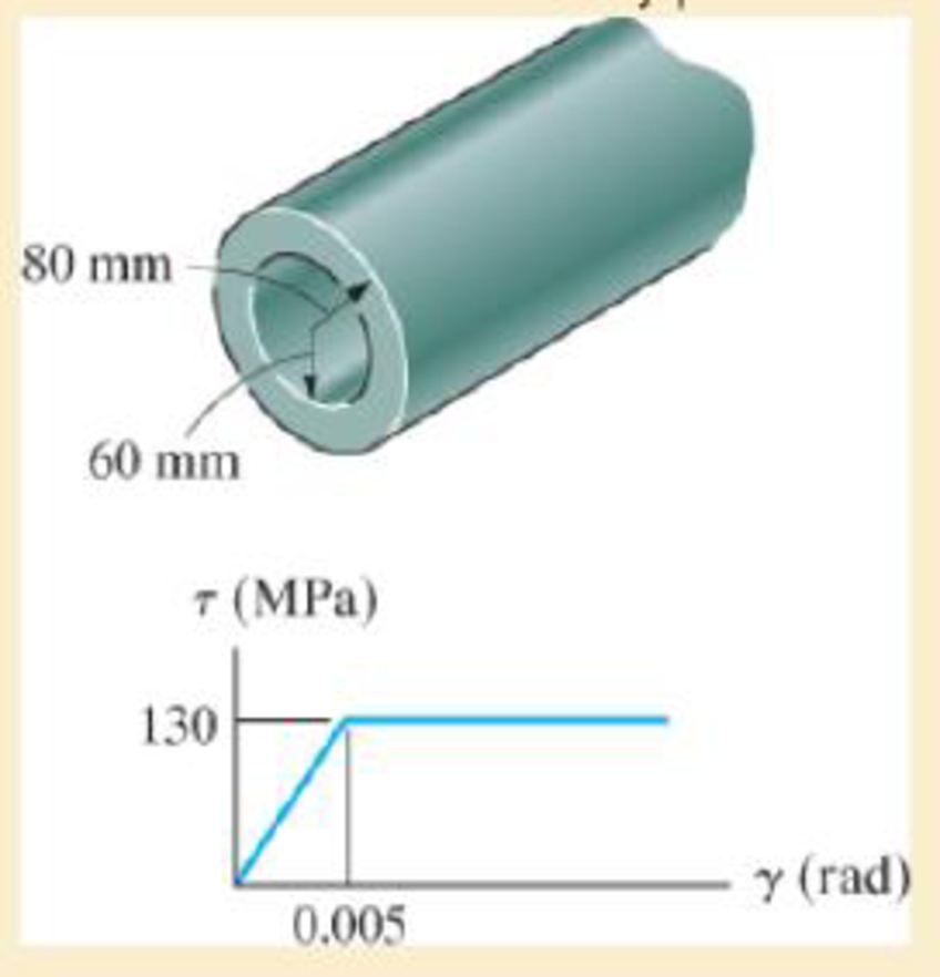
Chapter 5.10, Problem 5.134P
Determine the torque needed to just cause the material to become fully plastic. What is the permanent angle of twist of the tube when this torque is removed?
Expert Solution & Answer
Want to see the full answer?
Check out a sample textbook solution
Students have asked these similar questions
11. From the figure below, what is the rolling resistance from each wheel if they share to carry a weight of 18.7 KN from the Bugatti Chiron car ?
What is the required Force for the said car to move if the car wheels have a diameter of 28 inches?
A motor is used to drive a gear assembly at 200 rpm. The main gear is in the center of a 1 m long (0.5 m to the left and right of the gear) 50 mm diameter solid circular shaft, and power is taken from the two shaft ends. 25 kW is taken on the left end and an unknown amount of power is taken at the right end.
the torque to the left side of the gear is?
maximum shear stress to left of gear?
If the maximum shear stress on the shaft to the right of the gear is 125 MPa, approximately how much power is being drawn off from the right side of the shaft?
The shaft can be made from 6061-T6 aluminum. It has adequate strength to withstand the loading conditions in the scenario, including the loading on the right side of the shaft.
true or false?
The answer is 1290N, but I am not entirely sure how they got there. However, I noticed that when I calculated the torques for the person and that of the ladder, my answer would be correct if I multiplied by sin(60) or cos (30) instead. Using the sum of these values, I would divide it by the length of the ladder and sin(30), which would give the correct answer, but I'm a bit confused as to why I need to take sin(60) or cos(30) to calculate the torques for the weight of the ladder and the human, but then use sin(30) when calculating the torque for the perpendicular force. I would appreciate a work through of the problem and some explanation for my difficulties above, thank you.
Chapter 5 Solutions
Mechanics of Materials (10th Edition)
Ch. 5.3 - Determine the internal torque at each section and...Ch. 5.3 - Determine the. internal torque at each section and...Ch. 5.3 - The solid and hollow shafts are each subjected to...Ch. 5.3 - The motor delivers 10 hp to the shaft. If it...Ch. 5.3 - The solid circular shaft is subjected to an...Ch. 5.3 - The hollow circular shaft is subjected to an...Ch. 5.3 - The shaft is hollow from A to B and solid from B...Ch. 5.3 - Determine the maximum shear stress in the...Ch. 5.3 - Determine the maximum shear stress in the shaft at...Ch. 5.3 - Determine the shear stress a: point A on the...
Ch. 5.3 - The solid 50-mm-diameter shaft is subjected to the...Ch. 5.3 - The gear motor can develop 3 hp when it turns at...Ch. 5.3 - The solid shaft of radius r is subjected to a...Ch. 5.3 - The solid shaft of radius r is subjected to a...Ch. 5.3 - A shaft is made of an aluminum alloy having an...Ch. 5.3 - The copper pipe has an outer diameter of 40 mm and...Ch. 5.3 - The copper pipe has an outer diameter of 2.50 in....Ch. 5.3 - The solid aluminum shaft has a diameter of 50 mm...Ch. 5.3 - The solid aluminum shaft has a diameter of 50 mm....Ch. 5.3 - The solid 30-mm-diameter shaft is used to transmit...Ch. 5.3 - The solid shaft is fixed to the support at C and...Ch. 5.3 - The link acts as part of the elevator control for...Ch. 5.3 - The assembly consists of two sections of...Ch. 5.3 - The shaft has an outer diameter of 100 mm and an...Ch. 5.3 - The shaft has an outer diameter of 100 mm and an...Ch. 5.3 - A steel tube having an outer diameter of 2.5 in....Ch. 5.3 - If the gears are subjected to the torques shown,...Ch. 5.3 - If the gears are subjected to the torques shown,...Ch. 5.3 - The rod has a diameter of 1 in. and a weight of 10...Ch. 5.3 - The rod has a diameter of 1 in. and a weight of 15...Ch. 5.3 - The copper pipe has an outer diameter of 3 in. and...Ch. 5.3 - The copper pipe has an outer diameter of 3 in. and...Ch. 5.3 - The 60-mm-diameter solid shaft is subjected to the...Ch. 5.3 - The 60-mm-diameter solid shaft is subjected to the...Ch. 5.3 - The solid shaft is subjected to the distributed...Ch. 5.3 - The 60-mm-diameter solid shaft is subjected to the...Ch. 5.3 - The solid shaft is subjected to the distributed...Ch. 5.3 - The pipe has an outer radius r0 and inner radius...Ch. 5.3 - The drive shaft AB of an automobile is made of a...Ch. 5.3 - The drive shaft AB of an automobile is to be...Ch. 5.3 - Prob. 5.29PCh. 5.3 - The motor delivers 50 hp while turning at a...Ch. 5.3 - The solid steel shaft AC has a diameter of 25 mm...Ch. 5.3 - The pump operates using the motor that has a power...Ch. 5.3 - The gear motor can develop 110 hp when it turns at...Ch. 5.3 - The gear motor can develop 110 hp when it turns at...Ch. 5.3 - The gear motor can develop 14 hp when it turns at...Ch. 5.3 - The gear motor can develop 2 hp when it turns at...Ch. 5.3 - The 6-hp reducer motor can turn at 1200 rev/min....Ch. 5.3 - The 6-hp reducer motor can turn at 1200 rev/min....Ch. 5.3 - Prob. 5.39PCh. 5.3 - Prob. 5.40PCh. 5.3 - The A-36 steel tubular shaft is 2 m long and has...Ch. 5.3 - Prob. 5.42PCh. 5.3 - The solid shaft has a linear taper from rA at one...Ch. 5.3 - The 1-in.-diameter bent rod is subjected to the...Ch. 5.3 - The 1-in.-diameter bent rod is subjected to the...Ch. 5.3 - A motor delivers 500 hp to the shaft, which is...Ch. 5.4 - The 60 mm-diameter steel shaft is subjected to the...Ch. 5.4 - Prob. 5.10FPCh. 5.4 - The hollow 6061-T6 aluminum shaft has an outer and...Ch. 5.4 - A series of gears are mounted on the...Ch. 5.4 - The 80-mm-diameter shaft is made of steel. If it...Ch. 5.4 - The 80-mm-diameter shaft is made of steel. If it...Ch. 5.4 - The propellers of a ship are connected to an A-36...Ch. 5.4 - Show that the maximum shear strain in the shaft is...Ch. 5.4 - Determine the angle of twist of end B with respect...Ch. 5.4 - Determine the absolute maximum shear stress in the...Ch. 5.4 - Determine the maximum allowable torque T. Also,...Ch. 5.4 - If the allowable shear stress is allow = 80 MPa,...Ch. 5.4 - Determine the angle of twist of the end A.Ch. 5.4 - If gear B supplies 15 kW of power, while gears A,...Ch. 5.4 - If the shaft is made of steel with the allowable...Ch. 5.4 - Prob. 5.56PCh. 5.4 - If the rotation of the 100-mm-diameter A-36 steel...Ch. 5.4 - If the rotation of the 100-mm-diameter A-36 steel...Ch. 5.4 - It has a diameter of 1 in. and is supported by...Ch. 5.4 - Prob. 5.60PCh. 5.4 - Determine the absolute maximum shear stress in the...Ch. 5.4 - If the rotation of the 100-mm-diameter A992 steel...Ch. 5.4 - If the mixer is connected to an A-36 steel tubular...Ch. 5.4 - If the mixer is connected to an A-36 steel tubular...Ch. 5.4 - Also, calculate the absolute maximum shear stress...Ch. 5.4 - When it is rotating at 80 rad/s. it transmits 32...Ch. 5.4 - It is required to transmit 35 kW of power from the...Ch. 5.4 - Determine the angle of twist at end A. The shear...Ch. 5.4 - If a torque of T = 50 N m is applied to the bolt...Ch. 5.4 - If a torque of T= 50N m is applied to the bolt...Ch. 5.4 - If the motor delivers 4 MW of power to the shaft...Ch. 5.4 - Determine the angle of twist at the free end A of...Ch. 5.4 - Prob. 5.73PCh. 5.4 - Prob. 5.74PCh. 5.4 - Determine the angle of twist at the free end A of...Ch. 5.4 - If the shaft is subjected to a torque T at its...Ch. 5.5 - Gst = 75 GPa.Ch. 5.5 - The A992 steel shaft has a diameter of 60 mm and...Ch. 5.5 - If the shaft is fixed at its ends A and B and...Ch. 5.5 - and a thickness of 0.125 in. The coupling on it at...Ch. 5.5 - The coupling on it at C is being tightened using...Ch. 5.5 - The shaft is made of L2 tool steel, has a diameter...Ch. 5.5 - The shaft is made of L2 tool steel, has a diameter...Ch. 5.5 - If the allowable shear stresses for the magnesium...Ch. 5.5 - If a torque of T = 5 kNm is applied to end A,...Ch. 5.5 - Each has a diameter of 25 mm and they are...Ch. 5.5 - Each has a diameter of 25 mm and they are...Ch. 5.5 - It is fixed at its ends and subjected to a torque...Ch. 5.5 - 5–89. Determine the absolute maximum shear stress...Ch. 5.5 - Each has a diameter of 1.5 in. and they are...Ch. 5.5 - The shaft is subjected to a torque of 800 lbft....Ch. 5.5 - The shaft is made of 2014-T6 aluminum alloy and is...Ch. 5.5 - The tapered shaft is confined by the fixed...Ch. 5.5 - Determine the reactions at the fixed supports A...Ch. 5.7 - If the yield stress for brass is Y = 205 MPa,...Ch. 5.7 - By what percentage is the shaft of circular cross...Ch. 5.7 - Prob. 5.97PCh. 5.7 - If it is subjected to the torsional loading,...Ch. 5.7 - Solve Prob.5-98 for the maximum shear stress...Ch. 5.7 - determine the maximum shear stress in the shaft....Ch. 5.7 - If the shaft has an equilateral triangle cross...Ch. 5.7 - by 2 in. square cross section, and it is subjected...Ch. 5.7 - is applied to the tube If the wall thickness is...Ch. 5.7 - If it is 2 m long, determine the maximum shear...Ch. 5.7 - Also, find the angle of twist of end B. The shaft...Ch. 5.7 - Also, find the corresponding angle of twist at end...Ch. 5.7 - If the solid shaft is made from red brass C83400...Ch. 5.7 - If the solid shaft is made from red brass C83400...Ch. 5.7 - The tube is 0.1 in. thick.Ch. 5.7 - Prob. 5.110PCh. 5.7 - Determine the average shear stress in the tube if...Ch. 5.7 - By what percentage is the torsional strength...Ch. 5.7 - Prob. 5.113PCh. 5.7 - Prob. 5.114PCh. 5.7 - If the allowable shear stress is allow = 8 ksi,...Ch. 5.7 - Prob. 5.116PCh. 5.7 - If the allowable shear stress is allow = 80 MPa,...Ch. 5.7 - If the applied torque is T = 50 Nm, determine the...Ch. 5.7 - If it is subjected to a torque of T = 40 Nm....Ch. 5.10 - If the transition between the cross sections has a...Ch. 5.10 - Prob. 5.121PCh. 5.10 - If the radius of the fillet weld connecting the...Ch. 5.10 - Prob. 5.123PCh. 5.10 - Determine the maximum shear stress in the shaft. A...Ch. 5.10 - Prob. 5.125PCh. 5.10 - Determine the radius of the elastic core produced...Ch. 5.10 - Assume that the material becomes fully plastic.Ch. 5.10 - diameter is subjected to a torque of 100 in.kip....Ch. 5.10 - Determine the torque T needed to form an elastic...Ch. 5.10 - Determine the torque applied to the shaft.Ch. 5.10 - Prob. 5.131PCh. 5.10 - Determine the ratio of the plastic torque Tp to...Ch. 5.10 - Determine the applied torque T, which subjects the...Ch. 5.10 - Determine the torque needed to just cause the...Ch. 5.10 - Determine the radius of its elastic core if it is...Ch. 5.10 - Plot the shear-stress distribution acting along a...Ch. 5.10 - If the material obeys a shear stress-strain...Ch. 5.10 - It is made of an elastic perfectly plastic...Ch. 5.10 - Prob. 5.139PCh. 5.10 - Prob. 5.140PCh. 5.10 - is made from an elastic perfectly plastic material...Ch. 5.10 - Prob. 5.142PCh. 5.10 - If the materials have the diagrams shown,...Ch. 5.10 - Determine the torque required to cause a maximum...Ch. 5 - The shaft is made of A992 steel and has an...Ch. 5 - The shaft is made of A992 steel and has an...Ch. 5 - Determine the shear stress at the mean radius p =...Ch. 5 - If the thickness of its 2014-T6-aluminum skin is...Ch. 5 - Determine which shaft geometry will resist the...Ch. 5 - If couple forces P = 3 kip are applied to the...Ch. 5 - If the allowable shear stress for the aluminum is...Ch. 5 - Determine the angle of twist of its end A if it is...Ch. 5 - This motion is caused by the unequal belt tensions...
Knowledge Booster


Learn more about
Need a deep-dive on the concept behind this application? Look no further. Learn more about this topic, mechanical-engineering and related others by exploring similar questions and additional content below.Similar questions
- Read the question carefully and give me all right solutions. Internal torque at rod 1 (kip-ft) Magnitude of shear at rod 2 & 3(ksi) Rotation angle at rod 1 (deg) Rotation angle at flange C (deg)arrow_forwardWhat Fundamental problems occur in finding the resultant Internal normal force?arrow_forwardPlease help me solve this. I need answer asap. Tysm!! A flanged bolt coupling consists of eight d-mm diameter steel bolts on a bolt circle 275 mm in diameter, and four d-mm diameter steel bolts on a concentric bolt circle 193 mm in diameter. If the torque that can be applied is 9821 Nm without exceeding a shearing stress of 54.36 MPa in the bolts, what is the diameter of the bolts? Round off the final answer to two decimal places.arrow_forward
- If the torque is 2270 Nm, what is the minimum diameter solid shaft (in mm) to keep the stress under 203 Mpa ? 42.05 mm O 15.73 mm 38.47 mm O 23.11 mmarrow_forwardHow did you get the summation of forces in each direction?arrow_forwardselect the diameter of the cylinder to be used from L=150mm, if it is required to apply a force of 350 kg for a pneumatic die-cutting press. use the SMC analytical mathematical calculation method, clearly indicating the considerations and criteria used in the calculation. P=80psiarrow_forward
- The required information is in the attachment. Part A) If the load is at L2 = 4.7 m and the angle of twist at C is ϕC = 1.5 deg, what is the magnitude of the applied torque? Express your answer with appropriate units to three significant figures. Part B) If the applied torque is TC = 525 N⋅m, and the torsional load is at L2 = 1.2 m, then what is the magnitude of the reaction at A? Express your answer with appropriate units to three significant figures. Part C) What is the maximum stress at any point along the length of the shaft from Part B? Express your answer with appropriate units to three significant figures.arrow_forward3- Draw Torque vs. angle oi twist for Cast Iron specimenarrow_forwardANSWER ASAP The worm gear rotating at 1250 rpm drives a worm wheel and whose velocity ratio is 12 to 1. A driving motor with 12 hp is used to supply the worm with worm pitch gear diameter of 3.5 in. Find the tangential force on the gear.arrow_forward
- Figure if the center of the thin disc is drawn 15 mm and released; assuming that there is no slip between the disc and the surface, what is the maximum speed that the disc will reach?arrow_forward3. The two identical shafts, 1 and 2, are built into supports at their left ends. Gears mounted on their right ends engage a third gear that is attached to shaft 3. Determine the torques in shafts 1 and 2 when the 500N -m torque is applied to shaft 3. 40 500 Nm 80 Dimensions in mm 4. A 4-ft-long tube with the cross section shown in the figure is made of aluminum. Find the torque that will cause a maximum shear stress of 10 000 psi. Use G = 4 x 10⁶ psi for aluminum. +4 in. → 0.04 in. 0.08 in.´ 5. Two steel springs are arranged in series as shown. The upper spring has 36 turns of 100-mm- diameter wire on a mean radius of 350 mm. The lower spring consists of 24 turns of 75-mm diameter wire on a mean radius of 245 mm. If the ultimate shearing stress in either spring must not exceed 692 MPa, (a) compute the maximum value of P and total elongation using factor of safety equal to 1.5. (b) What is the equivalent spring constant? Use G = 83 GPa. 2 of 2 4 in. wwwww.-arrow_forwardA 45 mm diameter shaft is made of steel with a yield strength of 400 MPa. A parallel key of size 14 mm wide and 9 mm thick made of steel with a yield of 340 MPa is to be used. Find the required length of key, if the shaft is loaded to transmit the maximum permissible torque. Use maximum shear stress theory and assume a factor of safety of 2.arrow_forward
arrow_back_ios
SEE MORE QUESTIONS
arrow_forward_ios
Recommended textbooks for you
 Elements Of ElectromagneticsMechanical EngineeringISBN:9780190698614Author:Sadiku, Matthew N. O.Publisher:Oxford University Press
 Mechanics of Materials (10th Edition)Mechanical EngineeringISBN:9780134319650Author:Russell C. HibbelerPublisher:PEARSON
 Thermodynamics: An Engineering ApproachMechanical EngineeringISBN:9781259822674Author:Yunus A. Cengel Dr., Michael A. BolesPublisher:McGraw-Hill Education
 Control Systems EngineeringMechanical EngineeringISBN:9781118170519Author:Norman S. NisePublisher:WILEY
 Mechanics of Materials (MindTap Course List)Mechanical EngineeringISBN:9781337093347Author:Barry J. Goodno, James M. GerePublisher:Cengage Learning
 Engineering Mechanics: StaticsMechanical EngineeringISBN:9781118807330Author:James L. Meriam, L. G. Kraige, J. N. BoltonPublisher:WILEY
Elements Of Electromagnetics
Mechanical Engineering
ISBN:9780190698614
Author:Sadiku, Matthew N. O.
Publisher:Oxford University Press
Mechanics of Materials (10th Edition)
Mechanical Engineering
ISBN:9780134319650
Author:Russell C. Hibbeler
Publisher:PEARSON
Thermodynamics: An Engineering Approach
Mechanical Engineering
ISBN:9781259822674
Author:Yunus A. Cengel Dr., Michael A. Boles
Publisher:McGraw-Hill Education
Control Systems Engineering
Mechanical Engineering
ISBN:9781118170519
Author:Norman S. Nise
Publisher:WILEY
Mechanics of Materials (MindTap Course List)
Mechanical Engineering
ISBN:9781337093347
Author:Barry J. Goodno, James M. Gere
Publisher:Cengage Learning
Engineering Mechanics: Statics
Mechanical Engineering
ISBN:9781118807330
Author:James L. Meriam, L. G. Kraige, J. N. Bolton
Publisher:WILEY
Understanding Torsion; Author: The Efficient Engineer;https://www.youtube.com/watch?v=1YTKedLQOa0;License: Standard YouTube License, CC-BY