
Vector Mechanics for Engineers: Statics and Dynamics
12th Edition
ISBN: 9781259638091
Author: Ferdinand P. Beer, E. Russell Johnston Jr., David Mazurek, Phillip J. Cornwell, Brian Self
Publisher: McGraw-Hill Education
expand_more
expand_more
format_list_bulleted
Concept explainers
Videos
Textbook Question
Chapter 5.1, Problem 5.20P
A built-up beam is constructed by nailing seven boards together as shown. The nails are equally spaced along the beam, and the beam supports a vertical load. As proved in
Expert Solution & Answer
Want to see the full answer?
Check out a sample textbook solution
Students have asked these similar questions
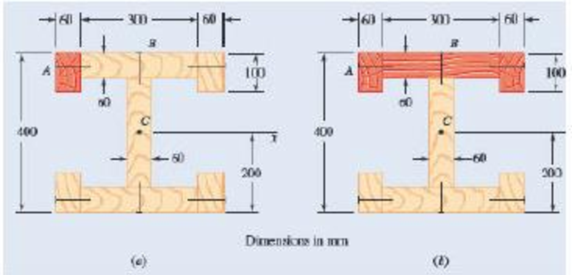
A composite beam is constructed by bolting four plates to four 60 × 60 × 12-mm angles as shown. The bolts are equally spaced along the beam, and the beam supports a vertical load. As proved in mechanics of materials, the shearing forces exerted on the bolts at A and B are proportional to the first moments with respect to the centroidal x axis of the red shaded areas shown, respectively, in parts a and b of the figure. Knowing that the force exerted on the bolt at A is 280 N, determine the force exerted on the bolt at B.
The wheels of a wagon can be approximated as the combination of a thin outer hoop, of radius r, = 0.262 m and mass
5.08 kg, and two thin crossed rods of mass 7.37 kg each. A farmer would like to replace his wheels with uniform disks
ta = 0.0462 m thick, made out of a material with a density of 7830 kg per cubic meter. If the new wheel is to have the same
%3D
moment of inertia about its center as the old wheel about its center, what should the radius of the disk be?
ra =
TOOLS
X10
A simply supported beam has a symmetrical rectangular cross-section. If thesecond moment of area (I) of a beam with a rectangular cross-section is 11.50 x 106 mm4 about its centroidal x-axis and the depth dimension (d) of the rectangular section is 180 mm, determine the breadth dimension (b) for this beam section. Give your answer in millimetres (mm) and to 2 decimal places. Assume the beam section material is homogeneous. (show all work)
Chapter 5 Solutions
Vector Mechanics for Engineers: Statics and Dynamics
Ch. 5.1 - 5.1 through 5.9 Locate the centroid of the plane...Ch. 5.1 - Locate the centroid of the plane area shown.Ch. 5.1 - Locate the centroid of the plane area shown.Ch. 5.1 - Locate the centroid of the plane area shown.Ch. 5.1 - Locate the centroid of the plane area shown.Ch. 5.1 - Locate the centroid of the plane area shown.Ch. 5.1 - Locate the centroid of the plane area shown.Ch. 5.1 - Locate the centroid of the plane area shown.Ch. 5.1 - Locate the centroid of the plane area shown.Ch. 5.1 - Locate the centroid of the plane area shown.
Ch. 5.1 - Locate the centroid of the plane area shown.Ch. 5.1 - Locate the centroid of the plane area shown.Ch. 5.1 - Locate the centroid of the plane area shown.Ch. 5.1 - Locate the centroid of the plane area shown.Ch. 5.1 - Locate the centroid of the plane area shown.Ch. 5.1 - PROBLEM 5.16 Determine the y coordinate of the...Ch. 5.1 - Show that as r1 approaches r2, the location of the...Ch. 5.1 - Prob. 5.18PCh. 5.1 - Prob. 5.19PCh. 5.1 - A built-up beam is constructed by nailing seven...Ch. 5.1 - The horizontal x axis is drawn through the...Ch. 5.1 - The horizontal x-axis is drawn through the...Ch. 5.1 - PROBLEM 5.23 The first moment of the shaded area...Ch. 5.1 - A thin, homogeneous wire is bent to form the...Ch. 5.1 - A thin, homogeneous wire is bent to form the...Ch. 5.1 - Prob. 5.26PCh. 5.1 - A thin, homogeneous wire is bent to form the...Ch. 5.1 - Prob. 5.28PCh. 5.1 - The frame for a sign is fabricated from thin, flat...Ch. 5.1 - The homogeneous wire ABCD is bent as shown and is...Ch. 5.1 - The homogeneous wire ABCD is bent as shown and is...Ch. 5.1 - Prob. 5.32PCh. 5.1 - Knowing that the distance h has been selected to...Ch. 5.2 - Determine by direct integration the centroid of...Ch. 5.2 - 5.34 through 5.36 Determine by direct integration...Ch. 5.2 - 5.34 through 5.36 Determine by direct integration...Ch. 5.2 - 5.37 through 5.39 Determine by direct integration...Ch. 5.2 - 5.37 through 5.39 Determine by direct integration...Ch. 5.2 - Prob. 5.39PCh. 5.2 - 5.40 and 5.41 Determine by direct integration the...Ch. 5.2 - 5.40 and 5.41 Determine by direct integration the...Ch. 5.2 - 5.42 Determine by direct integration the centroid...Ch. 5.2 - 5.43 and 5.44 Determine by direct integration the...Ch. 5.2 - 5.43 and 5.44 Determine by direct integration the...Ch. 5.2 - 5.45 and 5.46 A homogeneous wire is bent into the...Ch. 5.2 - 5.45 and 5.46 A homogeneous wire is bent into the...Ch. 5.2 - A homogeneous wire is bent into the shape shown....Ch. 5.2 - 5.48 and 5.49 Determine by direct integration the...Ch. 5.2 - Prob. 5.49PCh. 5.2 - Prob. 5.50PCh. 5.2 - Determine the centroid of the area shown when a =...Ch. 5.2 - Determine the volume and the surface area of the...Ch. 5.2 - Determine the volume and the surface area of the...Ch. 5.2 - Determine the volume and the surface area of the...Ch. 5.2 - Determine the volume and the surface area of the...Ch. 5.2 - Determine the volume of the solid generated by...Ch. 5.2 - Prob. 5.57PCh. 5.2 - Prob. 5.58PCh. 5.2 - Prob. 5.59PCh. 5.2 - Determine the capacity, in liters, of the punch...Ch. 5.2 - Determine the volume and total surface area of the...Ch. 5.2 - Prob. 5.62PCh. 5.2 - Determine the total surface area of the solid...Ch. 5.2 - Determine the volume of the brass collar obtained...Ch. 5.2 - The shade for a wall-mounted light is formed from...Ch. 5.3 - 5.66 and 5.67 For the beam and loading shown,...Ch. 5.3 - 5.66 and 5.67 For the beam and loading shown,...Ch. 5.3 - 5.68 through 5.73 Determine the reactions at the...Ch. 5.3 - 5.68 through Determine the reactions at the beam...Ch. 5.3 - 5.68 through 5.73 Determine the reactions at the...Ch. 5.3 - 5.68 through Determine the reactions at the beam...Ch. 5.3 - 5.68 through 5.73 Determine the reactions at the...Ch. 5.3 - 5.68 through 5.73 Determine the reactions at the...Ch. 5.3 - Determine (a) the distance a so that the vertical...Ch. 5.3 - Prob. 5.75PCh. 5.3 - Determine the reactions at the beam supports for...Ch. 5.3 - Determine (a) the distributed load w0 at the end D...Ch. 5.3 - The beam AB supports two concentrated loads and...Ch. 5.3 - For the beam and loading of Prob. 5.78, determine...Ch. 5.3 - The cross section of a concrete dam is as shown....Ch. 5.3 - Prob. 5.81PCh. 5.3 - The dam for a lake is designed to withstand the...Ch. 5.3 - Prob. 5.83PCh. 5.3 - The friction force between a 6 6-ft square sluice...Ch. 5.3 - A freshwater marsh is drained to the ocean through...Ch. 5.3 - Prob. 5.86PCh. 5.3 - The 3 4-m side of an open tank is hinged at its...Ch. 5.3 - Prob. 5.88PCh. 5.3 - A 0.5 0.8-m gate AB is located at the bottom of a...Ch. 5.3 - Prob. 5.90PCh. 5.3 - Prob. 5.91PCh. 5.3 - Prob. 5.92PCh. 5.3 - Prob. 5.93PCh. 5.3 - Prob. 5.94PCh. 5.3 - The square gate AB is held in the position shown...Ch. 5.4 - Consider the composite body shown. Determine (a)...Ch. 5.4 - A cone and a cylinder of the same radius a and...Ch. 5.4 - Determine the location of the center of gravity of...Ch. 5.4 - Prob. 5.99PCh. 5.4 - For the stop bracket shown, locate the x...Ch. 5.4 - Fig. P5.100 and P5.101 5.101 For the stop bracket...Ch. 5.4 - For the machine element shown, locate the x...Ch. 5.4 - Fig. P5.102 and P5.103 5.103 For the machine...Ch. 5.4 - For the machine element shown, locate the y...Ch. 5.4 - For the machine element shown, locate the x...Ch. 5.4 - 5.106 and 5.107 Locate the center of gravity of...Ch. 5.4 - 5.106 and 5.107 Locate the center of gravity of...Ch. 5.4 - A corner reflector for tracking by radar has two...Ch. 5.4 - A wastebasket, designed to fit in the corner of a...Ch. 5.4 - Prob. 5.110PCh. 5.4 - Prob. 5.111PCh. 5.4 - Prob. 5.112PCh. 5.4 - Locate the center of gravity of the sheet-metal...Ch. 5.4 - A thin steel wire with a uniform cross section is...Ch. 5.4 - The frame of a greenhouse is constructed from...Ch. 5.4 - Locate the center of gravity of the figure shown,...Ch. 5.4 - PROBLEM 5.117 Locate the center of gravity of the...Ch. 5.4 - A scratch awl has a plastic handle and a steel...Ch. 5.4 - Prob. 5.119PCh. 5.4 - PROBLEM 5.120 A brass collar, of length 2.5 in.,...Ch. 5.4 - Prob. 5.121PCh. 5.4 - Prob. 5.122PCh. 5.4 - Prob. 5.123PCh. 5.4 - Prob. 5.124PCh. 5.4 - PROBLEM 5.125 Locate the centroid of the volume...Ch. 5.4 - PROBLEM 5.126 Locate the centroid of the volume...Ch. 5.4 - Prob. 5.127PCh. 5.4 - Prob. 5.128PCh. 5.4 - PROBLEM 5.129 Locate the centroid of the volume...Ch. 5.4 - Prob. 5.130PCh. 5.4 - Prob. 5.131PCh. 5.4 - PROBLEM 5.132 The sides and the base of a punch...Ch. 5.4 - Locate the centroid of the section shown, which...Ch. 5.4 - Prob. 5.134PCh. 5.4 - Prob. 5.135PCh. 5.4 - Alter grading a lot, a builder places four stakes...Ch. 5 - 5.137 and 5.138 Locate the centroid of the plane...Ch. 5 - 5.137 and 5.138 Locate the centroid of the plane...Ch. 5 - Prob. 5.139RPCh. 5 - Prob. 5.140RPCh. 5 - Prob. 5.141RPCh. 5 - Prob. 5.142RPCh. 5 - Determine the reactions at the supports for the...Ch. 5 - A beam is subjected to a linearly distributed...Ch. 5 - Prob. 5.145RPCh. 5 - Prob. 5.146RPCh. 5 - An 8-in.-diameter cylindrical duct and a 4 8-in....Ch. 5 - Three brass plates are brazed to a steel pipe to...
Knowledge Booster


Learn more about
Need a deep-dive on the concept behind this application? Look no further. Learn more about this topic, mechanical-engineering and related others by exploring similar questions and additional content below.Similar questions
- Draw the shearing-force and bending-moment diagrams for the following beams: 1. A cantilever of length 20 m carrying a load of 10 kN at a distance of 15 m from the supported end. 2. A cantilever of length 20 m carrying a load of 10 kN is uniformly distributed over the inner 15 m of its length. 3. A cantilever of length 12 m carrying a load of 8 kN, applied 5 m from the supported end, and a load of 2kNlm over its whole length.arrow_forwardProblem (4.18): A vessel has a length of 60 m, width 12 m and a displacement of 19620 kN. When a eight of294.3 KN is rolled off transversely across the deck through a distance of 6.5 m, the vessel mts through S°. The second moment of area of the water line section about its fore-and-oft axis is 75 per cent of that of the circumscribing rectangle. The center of buoyancy is 2.75 m below the water line. Find: (i) The metacentric height (ii) The position of center of gravity of the vessel. Take specific weight of sea water 10.104 kN/m* [Ans. (i) 1.1145 m (ii) 0.53 m below water surface]arrow_forwardFor the shown frame structure, the uniform beam AB weighs 580 lb and the uniform column CF weighs 1,420 lb. If the dimensions a = 3.4 ft, b = 8.6 ft, and c = 4.7 ft, determine the magnitude of the bending moment (in lb*ft) at point E. Answer must include 1 place after the decimal point and proper units.arrow_forward
- The properties of the unequal angle section are Ix=80.9in.4,Iy=38.8in.4, and Iu=21.3in.4. Determine Ixy.arrow_forward2. Four forces are applied to the machine element ABDE as shown to the left. Find the resultant 200 mm force and the resultant moment at point A. (Assume that points A, B, D, and E are located at the centroid of the cross-section of the bar, and that the forces act at these points.) 50 N 40 mm 20 mm B. 300 N R =-420î – 50ĵ– 250k N Ans.: 160 mm M, =0î +30.8ĵ –22k N - m 250 N D A 100 mm E 120 Narrow_forwardA simply supported beam has a symmetrical rectangular cross-section. If the second moment of area (I) of a beam with a rectangular cross-section is 11.50 x 106 mm4 about its centroidal x-axis and the depth dimension (d) of the rectangular section is 180 mm, determine the breadth dimension (b) for this beam section. Give your answer in millimetres (mm) and to 2 decimal places. Assume the beam section material is homogeneous.arrow_forward
- Calculate the moment of the 90-N force about point o for the condition 0 = 15°, Also, determine the value of 0 for which the moment about 0 is (b)zero and (c ) a maximum., from the following answers which of them is correct: F = 90 N 800 mm 600 mm %3D 217), (c) 0 = 126.9 (or 307) %3D a) Mo =33.5 N.m CCW, (b) 0 = 36.9 (or 227), (c) 0 = 126.9 (or 317) %3D %3D 257), (c) 0 = 126.9 (or 347) %3D a) Mo =33.5 N.m CCW, (b) 0 = 36.9 (or 237), (c) 0 = 126.9 (or 327) %D а) Мо %333.5 N.m CCW, (b) ө - 36.9 (or 247), (c) 0 = 126.9 (or 337)arrow_forwardQ2 :The railway wheel exerts a force on the rail and through the wooden beam, and the gravel can be assumed as a reaction over the length of the wooden beam, as shown in Fig. Q2. (a) Draw the shear force and bending moment diagrams for the beam and determine the magnitude of the maximum load w per kN/m. (b) If the allowable bending stress is 10 MN/m² and the aspect ratio of the rectangular wood beam is h/b = 0.5, determine the minimum width b and height h that can be used for the beam. 60 kN Į 45 cm 60 KN Uniform Reaction w kN/m 150 cm 45 cm Fig. Q2 Railway Loadingarrow_forwardDetermine the reactions at A for the cantilever beam subjected to the distributed and concentrated loads. 3.0 kN 6.7 kN/m 3.7 m 1.8 m 1.8 m Part 1 The free-body diagram of the body is shown. The distributed loading has been replaced with a single equivalent force R at a distance d to the right of point A. Find the magnitude of the force R and the distance d. R 3.0 kN d Answer: R = i kN d = i marrow_forward
- Use the graphical method to construct the shear-force and bending-moment diagrams for the beam shown. Let a -5 m, b = 3 m, Pg - 55 kN, Pc-75 kN, and PE - 25 kN. Construct the shear-force and bending-moment diagrams on paper and use the results to answer the questions in the subsequent parts of this GO exercise. a Ay= 41.54 Answers: a B (a) V- i (b) V= (c) V= i (d) V- i i a Calculate the reaction forces A, and Dy acting on the beam. Positive values for the reactions are indicated by the directions of the red arrows shown on the free-body diagram below. (Note: Since Ax = 0, it has been omitted from the free-body diagram.) B C a b C Pc b D Dy D kN, Dy= 113.46 kN. a Determine the shear force acting at each of the following locations: (a) x = 2.5 m (b) x-7.5 m (c) x = 11.5 m (d) x = 15.5 m kN. When entering your answers, use the shear force sign convention. kN. a kN. E E x kN.arrow_forwardA cross section of a beam is bounded by the x-axis and the positive values of the function y = 4 – x. Find the coordinates of the centroid of the cross section.arrow_forwardDetermine the resultant of the line load acting on the beam shown in Fig. (a) Can u please help mearrow_forward
arrow_back_ios
SEE MORE QUESTIONS
arrow_forward_ios
Recommended textbooks for you
 International Edition---engineering Mechanics: St...Mechanical EngineeringISBN:9781305501607Author:Andrew Pytel And Jaan KiusalaasPublisher:CENGAGE L
International Edition---engineering Mechanics: St...
Mechanical Engineering
ISBN:9781305501607
Author:Andrew Pytel And Jaan Kiusalaas
Publisher:CENGAGE L
Understanding Stress Transformation and Mohr's Circle; Author: The Efficient Engineer;https://www.youtube.com/watch?v=_DH3546mSCM;License: Standard youtube license