
(a)
To select:
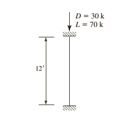
American standard channel for the given compression member using LRFD.
Answer to Problem 4.8.4P
Explanation of Solution
Given information:
Given compression member is :

Calculation:
Calculate the factored load by LRFD by using the equation.
Here
Substitute
Try a C section
AISC must be used, as this shape is non slender and is neither a double angle nor a tee shape
Check the effective slenderness ratio about y-axis using the formula.
Here K is the effective length factor
L is the length of the member between the supports.
r is the radius of gyration
Take the properties steel from the AISC steel table. K value depends on the end conditions
Calculate the elastic buckling stress using the formula.
Check for slenderness ratio by using the formula.
Here
Substitute
Since
Calculate the nominal compressive strength of column using the formula.
Substitute,
=
=
Calculate design strength of the column using by LRFD method
Here we have
Check the effective slenderness ratio about x-axis using the formula.
Substitute
From the manual companion CD:
Calculate the elastic buckling stress using the formula.
Calculate the value of
Calculate the total stress by equation
Calculate the value of
In order to determine which compressive strength equation to be use, compare the value of
Since
Calculate the maximum strength by using the formula.
.
Conclusion:
(b)
To select:
American standard channel for the given compression member using ASD.
Answer to Problem 4.8.4P
Explanation of Solution
Given information:
Given compression member is
Calculation:
Calculate the factored load by LRFD by using the equation.
He re
Substitute
Try a C section
AISC must be used, as this shape is non slender and is neither a double angle nor a tee shape
Check the effective slenderness ratio about y-axis using the formula
Here K is the effective length factor
L is the length of the member between the supports
r is the radius of gyration
Take the properties steel from the AISC steel table. K value depends on the end conditions
Calculate the elastic buckling stress using the formula.
Check for slenderness ratio by using the formula.
Here
Substitute
Since
Calculate the nominal compressive strength of column using the formula.
Substitute,
=
=
Calculate design strength of the column using by ASD method.
Here we have
Check the effective slenderness ratio about x-axis using the formula.
Substitute
From the manual companion CD:
Calculate the elastic buckling stress using the formula.
Calculate the value of
Calculate the total stress by equation
Calculate the value of
In order to determine which compressive strength equation to be use, compare the value of
Since
Calculate the maximum strength by using the formula.
Conclusion:
Want to see more full solutions like this?
Chapter 4 Solutions
Steel Design (Activate Learning with these NEW titles from Engineering!)

- A PL 38 X 6 tension member is welded to a gusset plate as shown. The steel is A36 (Fy = 36ksi, Fu = 58ksi). a. The design strength, Pu based on gross area b. The design strength, Pu based on effective area PL % x 6 3/8" 6" Cross Sectional area of PL3/8x6 a) Blank 1 b) Blank 2 Blank 1 Add your answer Blank 2 Add your answerarrow_forwardQ1:A: The Ix6 in. plate shown in Figure below is connected to a lx10 in. plate with longitudinal fillet welds to transfer a tensile load. Determine the LRFD design tensile strength of the member if F, = 50 ksi and Fu = 65 ksi. PLI X 10 in PL1 x 6 in P P w= 6 in Longitudinal fillet welds L=8 inarrow_forward4.3-4 Determine the available strength of the compression member shown in Figure P4.3-4. in each of the following ways: a. Use AISC Equation E3-2 or E3-3. Compute both the design strength for LRFD and the allowable strength for ASD. 15 HSS 10x6x ASTM A500, Grade B steel (Fy=46 ksi) 2/3arrow_forward
- The lap joint in the figure is fastened by four 20 mm Ø A325X bolts. Calculate the maximum safe load P that can be applied if the plates are 25 mm thick A-36 steel Use ASD. 4 @ 40 mm P 2 @ 60 mm Parrow_forwardA structural tee bracket is attached to a column flange with six bolts as shown in Figure . All structural steel is A992. Check this connection for compliance with the AISC Specification. Assume that the bearing strength is controlled by the bearing deformation strength of 2.4dtFu. a. Use LRFD. b. Use ASD.arrow_forwardA PL 38 X 6 tension member is welded to a gusset plate as shown. The steel is A36 (Fy = 36ksi, Fu = 58ksi). a. The design strength, Pu based on gross area b. The design strength, Pu based on effective area PL % x6 3/8" 6" Cross Sectional area of PL3/8x6 a) Blank 1 b) Blank 2arrow_forward
 Steel Design (Activate Learning with these NEW ti...Civil EngineeringISBN:9781337094740Author:Segui, William T.Publisher:Cengage Learning