
International Edition---engineering Mechanics: Statics, 4th Edition
4th Edition
ISBN: 9781305501607
Author: Andrew Pytel And Jaan Kiusalaas
Publisher: CENGAGE L
expand_more
expand_more
format_list_bulleted
Videos
Textbook Question
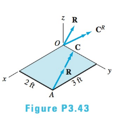
Chapter 3, Problem 3.43P
The force-couple system acting at O is equivalent to the wrench acting at A. If
Expert Solution & Answer

Trending nowThis is a popular solution!

Students have asked these similar questions
Given the Position vector
R = i+0j + k (m)
and the Force vector
F = 2i + 2j + 2k (kN)
Determine R. F
Answer:
Q: Represent the resultant of the three forces and one couple by an
equivalent force R at A and a couple M. find M and the magnitude and
direction ofR*
-30
400 lb
3'
1000 lb-ft
A
B
800 lb
6'-
300 lb
O R=677N, M-1131 ib-ft, theta= 41.2 degree
O R=675N, M=1136 ib-ft, theta= 42.2 degree
R=676N, M=1132 ib-ft, theta= 40.2 degree
Express and identify the resultant of the two forces and one couple shown acting on the shaft angled in the x-z plane.
Assume F = 350 lb, M = 310 lb-ft, a = 8 in., b = 22 in., 0 = 17%
10
F. a
-M
k) lb-in.
i
Answer:
M = (i
b
F
Ө
i+ i
j+
Chapter 3 Solutions
International Edition---engineering Mechanics: Statics, 4th Edition
Ch. 3 - Determine which of the force systems in (b)...Ch. 3 - Replace the force system acting on the beam by an...Ch. 3 - Replace the force system with an equivalent...Ch. 3 - The four forces shown act on the rollers of an...Ch. 3 - Replace the three forces with an equivalent...Ch. 3 - The force system acting on the machine part is...Ch. 3 - The three forces are perpendicular to the...Ch. 3 - Replace the three forces acting on the...Ch. 3 - When the three forces acting on the...Ch. 3 - Represent each of the force systems with a...
Ch. 3 - A worker applies the forces P=8i+10jlb and Q=8ilb...Ch. 3 - When the three forces are replaced by an...Ch. 3 - Replace the two forces and a couple acting on the...Ch. 3 - The shaft-and-pulley assembly ABCD is driven by...Ch. 3 - Replace the force and the couple with an...Ch. 3 - Determine the resultant force R and its line of...Ch. 3 - The 3200-1b weight is supported by two cables....Ch. 3 - The resultant of the three concurrent forces...Ch. 3 - The overhead electric hoist C rides along a track...Ch. 3 - Determine the resultant of the two forces and the...Ch. 3 - Determine the resultant of the force system shown.Ch. 3 - Determine the resultant of the three forces if (a)...Ch. 3 - Determine the resultant of the force system acting...Ch. 3 - Determine the resultant of the forces shown.Ch. 3 - The resultant of the three forces is a force R...Ch. 3 - The resultant of the four belt tensions and the...Ch. 3 - The resultant of the three forces shown is a...Ch. 3 - The resultant of the three forces is the force...Ch. 3 - The bar AB, which is inclined at the angle to the...Ch. 3 - The values of Fz,Mx, and My for three force...Ch. 3 - State whether the resultant of each force system...Ch. 3 - Determine the resultant of the three cable...Ch. 3 - The resultant of the three cable tensions acts...Ch. 3 - The resultant of the three forces acting along the...Ch. 3 - The resultant of the four forces that act on the...Ch. 3 - Determine the resultant R of the three forces...Ch. 3 - Find the resultant of the three forces acting on...Ch. 3 - The resultant of the forces P1,P2, and the couple...Ch. 3 - Find the resultant of the two forces and the...Ch. 3 - Determine the resultant of the force system acting...Ch. 3 - The wrench shown is the resultant of a...Ch. 3 - Determine the resultant of the four forces.Ch. 3 - The force-couple system acting at O is equivalent...Ch. 3 - The force-couple system consists of the force...Ch. 3 - (a) Replace the force system shown by an...Ch. 3 - During a storm, wind exerts a pressure of 110N/m2,...Ch. 3 - Water pressure acting on the vertical wall of the...Ch. 3 - Determine the resultant of the line load acting on...Ch. 3 - Determine the resultant of the line load acting on...Ch. 3 - Determine the resultant of the line loads acting...Ch. 3 - Find the resultant of the distributed load acting...Ch. 3 - Determine the resultant of the uniformly...Ch. 3 - The figure shows the water pressure acting on the...Ch. 3 - The water pressure acting on a masonry dam varies...Ch. 3 - The concrete pier is subjected to soil pressure...Ch. 3 - Find the resultant of the three forces acting on...Ch. 3 - The resultant of the force system shown is a...Ch. 3 - Determine the resultant of the three forces acting...Ch. 3 - The five forces act at end A of the boom....Ch. 3 - Find the resultant of the distributed load acting...Ch. 3 - Determine the resultant of the line loads acting...Ch. 3 - Replace the force system shown with an equivalent...Ch. 3 - The center of gravity of the 30-lb square plate is...Ch. 3 - Determine the resultant of the force system shown.Ch. 3 - Find the x- and y-coordinates of the point where...Ch. 3 - Replace the force system acting on the pipe with...Ch. 3 - Replace the coplanar force system that acts on the...Ch. 3 - Determine the magnitude of the resultant of the...Ch. 3 - Determine the wrench that is equivalent to the...Ch. 3 - The resultant of the three cable tensions acting...
Knowledge Booster


Learn more about
Need a deep-dive on the concept behind this application? Look no further. Learn more about this topic, mechanical-engineering and related others by exploring similar questions and additional content below.Similar questions
- Express and identify the resultant of the two forces and one couple shown acting on the shaft angled in the x-z plane. Assume F = 500 lb, M = 490 lb-ft, a = 8 in., b = 22 in., 0 = 12° -M Answer: M=(1 -21.52 j+ i 12.57 k) lb-in. 300arrow_forwardProblem 3 Determine the moment of the force F about an axis extending between A and C. (F= 4i + 12j 3k) lb Express the result as Cartesian vector. 4 ft 3 ft 2 ft A AF (4i + 12j3k) lbarrow_forwardIf the resultant of the two forces and couple * ?M passes through point O, Determine M 150 mm 150 M- 60° mm 30° 320 N 160 mm 400 N M= 148 N.m CCW M= 96 N.m CCW M= 148 N.m CW M= 96 N.m CWarrow_forward
- 4. A machine component is subjected to the forces and couples as shown. If P = 60 N, determine the magnitude and direction of the resultant force as well as the location where the resultant force passes through vertical line GF and horizontal line GH. 15 200 N 50 mm 520 mm E 50 mm 240 mm 42 N-m D 120 N 70⁰ 40 N-m 640 mm H 80 N 180 mm B +50mm Ans: (a) 0.365 m above G (b) 0.227 m to the right of Garrow_forwardDetermine the moment of the three forces about the point A. F = 30 lb F = 20 lb/ 30% 70° 50 lb < 60° 4 in. 1 in. -3.5 in:-arrow_forwardReplace the three forces shown by an equivalent force-couple system at point A. If the forces are replaced by a single resultant force, determine the distance d below point A to its line of action. 100 N 560 mm 560 mm 560 mm 260 N Answers: Force-couple system at A. The force is positive if to the right, and the couple is positive if counterclockwise. R= i N M = Single resultant force. d = i 120 N N•m mmarrow_forward
- The crowbar is subjected to a vertical force of P = 25 lb at the grip, whereas it takes a force of F = 155 lb at the claw to pull the nail out. Find the moment of each force about point A and determine if P is sufficient to pull out the nail. The crowbar contacts the board at point A. 20° 14 in. 60° 3 in. F 1.5 in.arrow_forwardAn angular bracket shown is acted upon by forces and a couple applied in the direction and location indicated. Locate the resultant (distance) from point A. A, H-90 N K W=140 N 200 mm 200 mm 100 mm 40° 400 mm P=80 N √√3 F-200 N W= 70Narrow_forwardThe pulley and gear are subjected to the loads shown. For these forces, determine the equivalent force-couple system at point O. 355 mm 285 110 mm mm 730 N 55 mm 215 N 15° 1215 N Answers: R = (i i+ i j+ i k) N Mo = ( i i+ i j+ i k) N-marrow_forward
- Express and identify the resultant of the two forces and one couple shown acting on the shaft angled in the x-z plane. Assume F = 490 lb, M = 470 lb-ft, a = 5 in., b = 12 in., 0 = 22° 10 a -M j+ i !k) lb-in. F. Answer: M = i F Ꮎ ! i+ i 5302arrow_forwardFive forces and a couple act on the plate shown in the figure . - Find the resultant ( R ) Of the four forces , and its angle (e). - Locate it with respect to point ( O). - Show where the resultant cuts both the x - and y- axes. 400KN 7m 1o0 KN 6 m lom 800 KN-m V150 KN 18m 7200KN 100 KN L 8 marrow_forwardGiven: F1={9 i - 9 j+ 10 k}lb F2={-10 i+10 j+ 10 k}lb Find: the Magnitude of the Resultant moment in (Ib.ft) generated by the forces about point O. 4 ft 5 ft 3 ftarrow_forward
arrow_back_ios
SEE MORE QUESTIONS
arrow_forward_ios
Recommended textbooks for you
 Elements Of ElectromagneticsMechanical EngineeringISBN:9780190698614Author:Sadiku, Matthew N. O.Publisher:Oxford University Press
 Mechanics of Materials (10th Edition)Mechanical EngineeringISBN:9780134319650Author:Russell C. HibbelerPublisher:PEARSON
 Thermodynamics: An Engineering ApproachMechanical EngineeringISBN:9781259822674Author:Yunus A. Cengel Dr., Michael A. BolesPublisher:McGraw-Hill Education
 Control Systems EngineeringMechanical EngineeringISBN:9781118170519Author:Norman S. NisePublisher:WILEY
 Mechanics of Materials (MindTap Course List)Mechanical EngineeringISBN:9781337093347Author:Barry J. Goodno, James M. GerePublisher:Cengage Learning
 Engineering Mechanics: StaticsMechanical EngineeringISBN:9781118807330Author:James L. Meriam, L. G. Kraige, J. N. BoltonPublisher:WILEY
Elements Of Electromagnetics
Mechanical Engineering
ISBN:9780190698614
Author:Sadiku, Matthew N. O.
Publisher:Oxford University Press
Mechanics of Materials (10th Edition)
Mechanical Engineering
ISBN:9780134319650
Author:Russell C. Hibbeler
Publisher:PEARSON
Thermodynamics: An Engineering Approach
Mechanical Engineering
ISBN:9781259822674
Author:Yunus A. Cengel Dr., Michael A. Boles
Publisher:McGraw-Hill Education
Control Systems Engineering
Mechanical Engineering
ISBN:9781118170519
Author:Norman S. Nise
Publisher:WILEY
Mechanics of Materials (MindTap Course List)
Mechanical Engineering
ISBN:9781337093347
Author:Barry J. Goodno, James M. Gere
Publisher:Cengage Learning
Engineering Mechanics: Statics
Mechanical Engineering
ISBN:9781118807330
Author:James L. Meriam, L. G. Kraige, J. N. Bolton
Publisher:WILEY
How to balance a see saw using moments example problem; Author: Engineer4Free;https://www.youtube.com/watch?v=d7tX37j-iHU;License: Standard Youtube License